Axial piston pump, and power transmission device with axial piston pump

a technology of axial piston and power transmission device, which is applied in the direction of piston pumps, positive displacement liquid engines, gas turbine engines, etc., can solve the problems of increasing the suction resistance of oil, the flow rate of oil suctioned by the pump, and the inability to change the pump capacity, so as to reduce the rotational difference between the input side and the output side, increase the pump capacity, and prevent the effect of pump energy loss

Inactive Publication Date: 2009-03-05
TOYOTA JIDOSHA KK
View PDF9 Cites 8 Cited by
  • Summary
  • Abstract
  • Description
  • Claims
  • Application Information

AI Technical Summary

Benefits of technology

[0012]According to this power transmission device, since the axial piston pump is interposed between the output side and input side of the power transmission path, the pump can be driven by the rotational difference between the input side and the output side to suction or discharge the oil. The cam device provided in this pump has the fixed cam member and the movable cam member that have different irregularity differences on the respective cam surfaces so that these cam members can be used separately depending on the traveling condition of the vehicle and the condition of the power source for traveling. In such a circumstance as the startup of the vehicle, where the rotational difference between the input side and the output side is significant, the flow rate of the oil suctioned by the pump can be prevented from increasing by reducing the pump capacity, whereby followability of the cam follower

Problems solved by technology

Therefore, the pump disclosed in JP-A-2006-233972 is not suitable for changing the pump capacity depending on the situation.
However, when such a pump is incorporated in an automatic transmission of a vehicle such as an automobile, and the input side and the output side of a power transmission path are connected to a drive shaft and a driven shaft of the pump, respectively, t

Method used


Image

  • Axial piston pump, and power transmission device with axial piston pump
  • Axial piston pump, and power transmission device with axial piston pump
  • Axial piston pump, and power transmission device with axial piston pump

Examples


Embodiment Construction

[0027]Example embodiments of the present invention will be described in greater detail below with reference to the accompanying drawings.

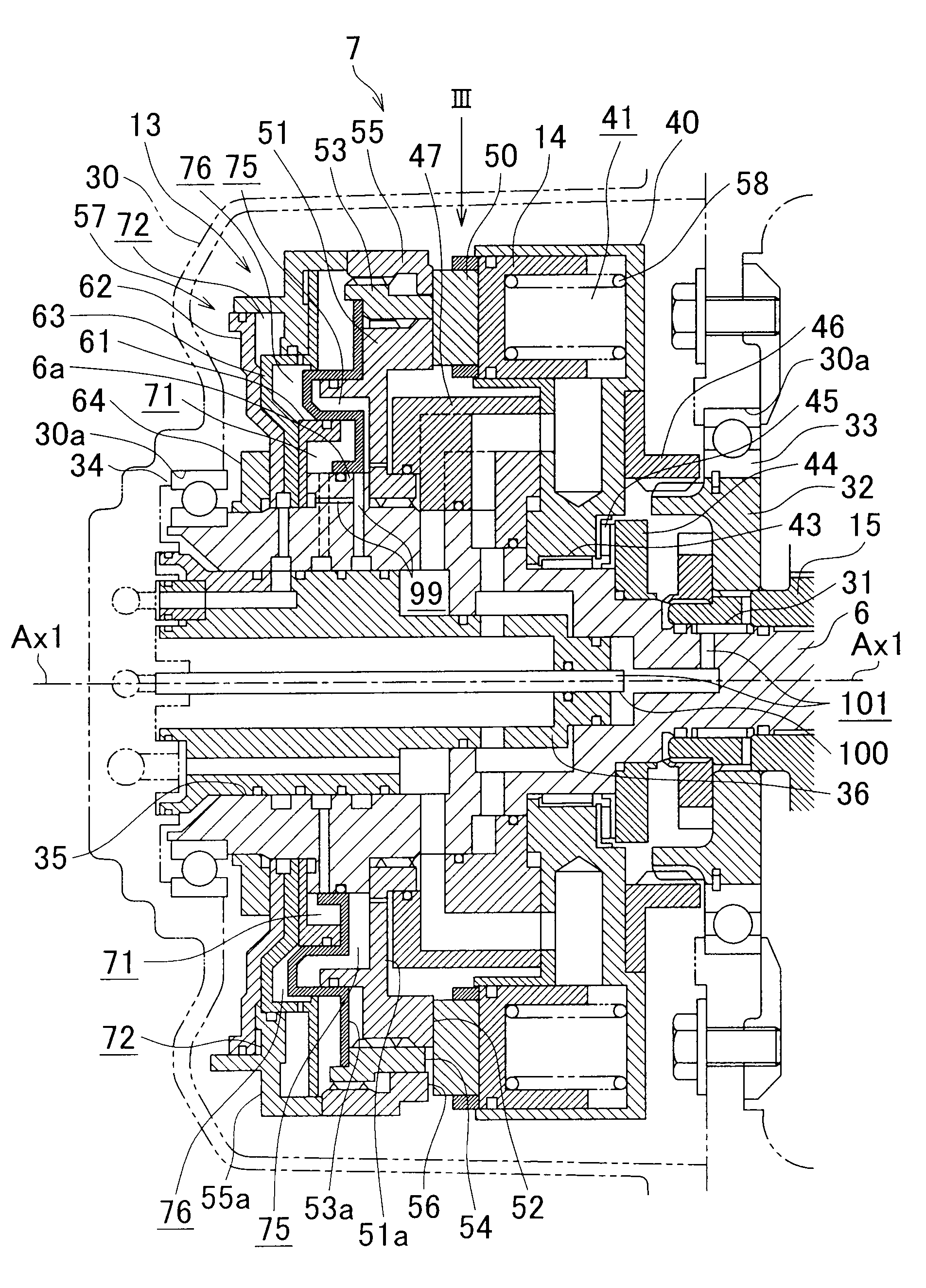
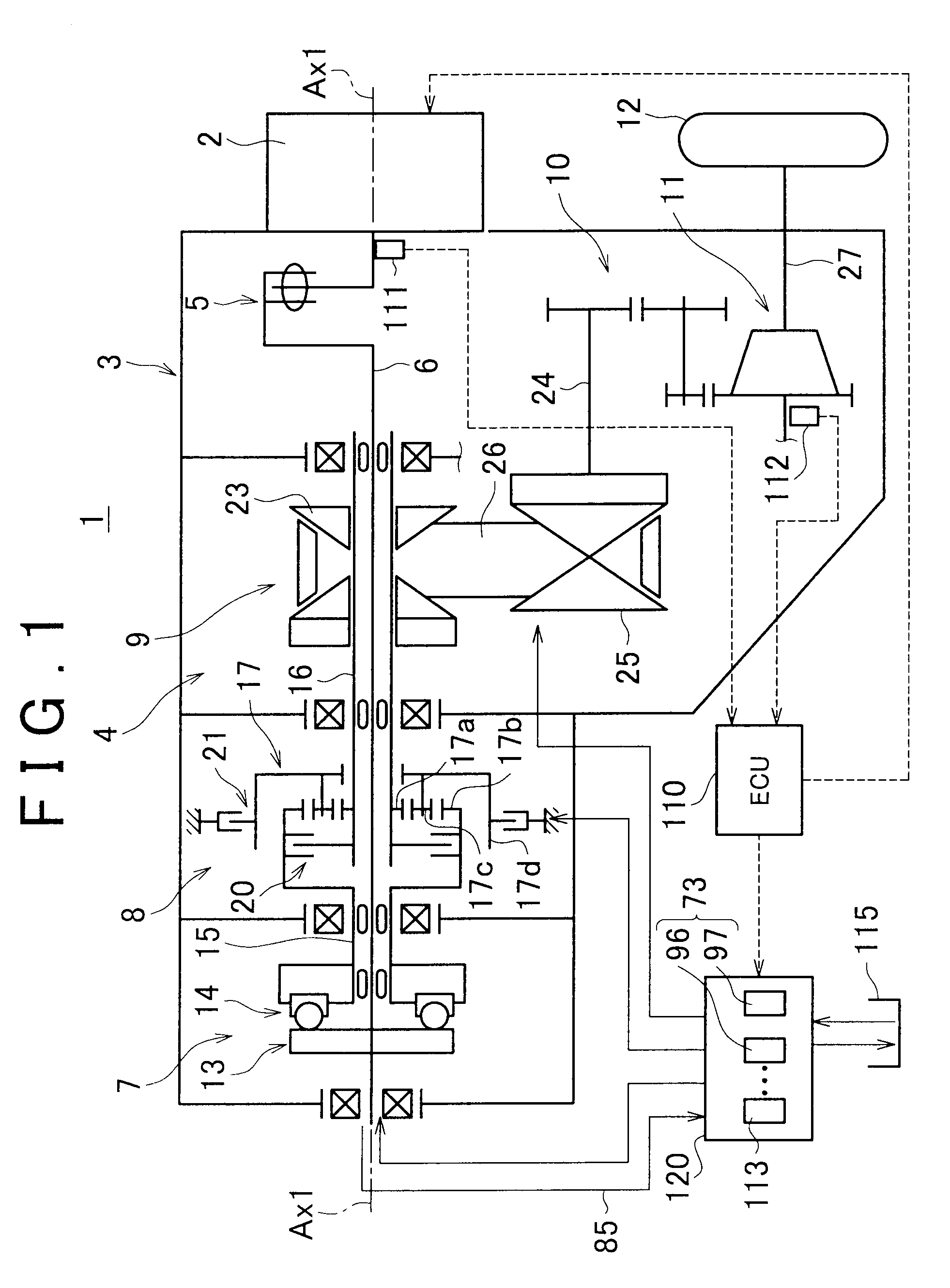
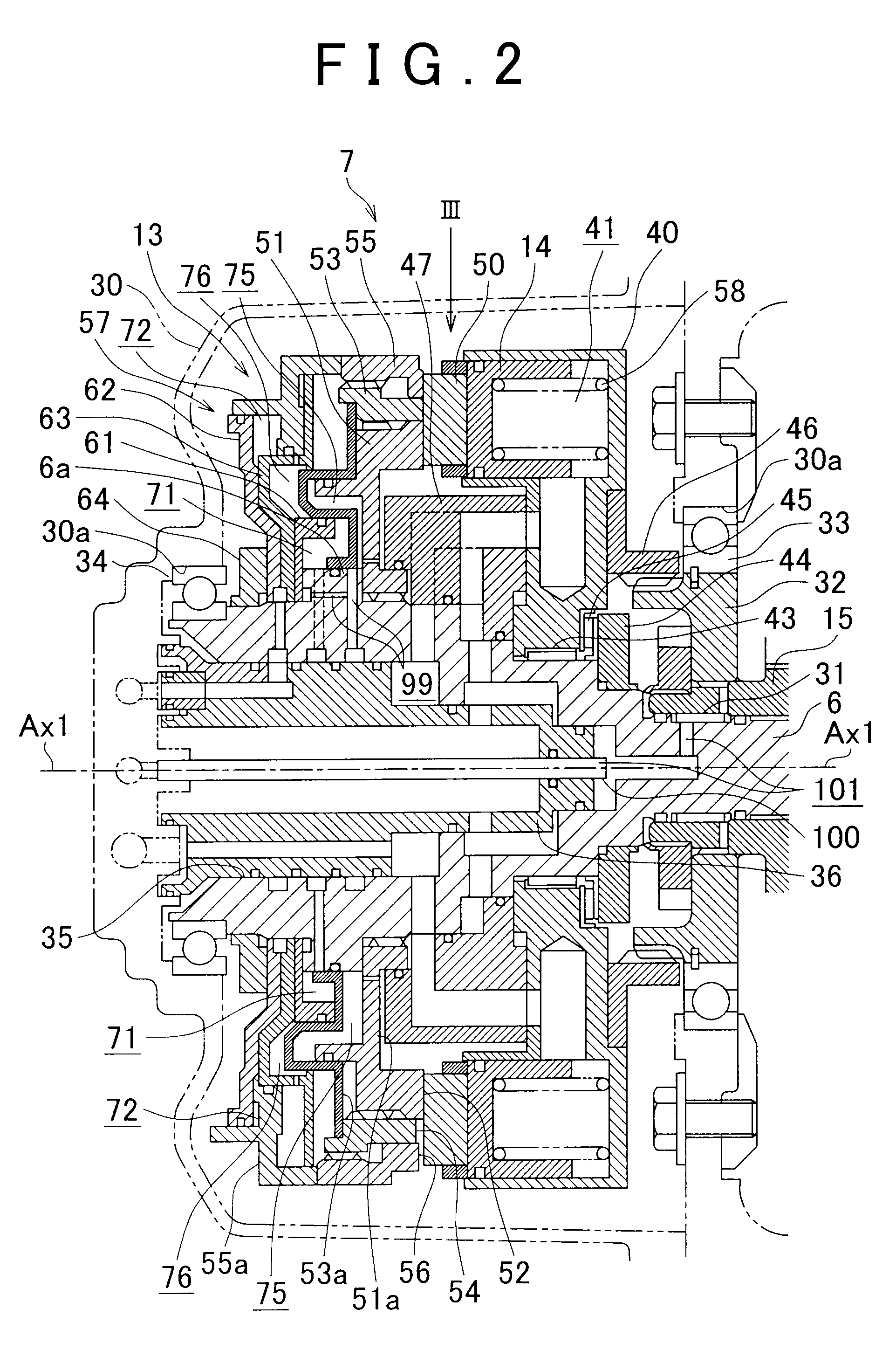
[0028]FIG. 1 is a skeleton diagram showing simplified power transmission path and other elements of a vehicle which is provided with a power transmission device incorporated with an axial piston pump related to an embodiment of the invention. A vehicle 1 is provided with an internal combustion engine 2 as its power source for traveling. An output torque of the internal combustion engine 2 is input to a power transmission device 4 accommodated in a casing 3 and then transmitted to a drive wheel 12 after gear change and other various operations are performed. The power transmission device 4 is configured such that a torque transmitted to an input shaft 6 via a damper mechanism 5 is transmitted to the drive wheel 12 via a pump 7, forward / reverse change-over device 8, continuously variable transmission 9, transmission device 10 and final reduction gear...


PUM


Abstract

An axial piston pump has: a cylinder body that forms therein a cylinder chamber extending in an axial direction of a drive shaft and rotates integrally with a driven shaft; a piston that reciprocates in the axial direction of the drive shaft; and a cam device that rotates integrally with the drive shaft and has: a fixed cam member that has a cam surface capable of coming into contact with a cam follower coupled to the piston and is capable of rotating integrally with the drive shaft, with movement of the fixed cam member in the axial direction being restricted; and a movable cam member that has a cam surface capable of coming into contact with the cam follower and is capable of rotating integrally with the drive shaft, with movement of the movable cam member in the axial direction being allowed, irregularity differences in the axial direction of the cam surface of the fixed cam member and the movable cam member being different from each other.

Description

INCORPORATION BY REFERENCE[0001]The disclosure of Japanese Patent Application No. 2007-225090 filed on Aug. 31, 2007, including the specification, drawings and abstract is incorporated herein by reference in its entirety.BACKGROUND OF THE INVENTION[0002]1. Field of the Invention[0003]This invention relates to an axial piston pump capable of reciprocating a piston provided in a cylinder chamber in an axial direction of a drive shaft by using cam device capable of rotating integrally with the drive shaft. The invention also relates to a power transmission device having the axial piston pump.[0004]2. Description of the Related Art[0005]There is a conventional multi-stroke type axial piston pump, which has cam members having cam surfaces facing in an axial direction of a drive shaft and rotating integrally with the drive shaft, and in which roller rolling on the cam surfaces are supported to pistons reciprocating in the axial direction (see Japanese Patent Application Publication No. 20...

Claims


Application Information

Patent Timeline
IPC IPC(8): F04B19/02F04B9/04
CPCY10T74/2102F04B1/14F04B1/145F04B1/146Y10T74/18304
Inventor KUWABARA, SHINYAFUJIYOSHI, TADASHISHIOIRI, HIROYUKI
Owner TOYOTA JIDOSHA KK
Why Eureka
Try Eureka