Battery assembly

Active Publication Date: 2009-03-05
TOYODA GOSEI CO LTD
View PDF8 Cites 71 Cited by
  • Summary
  • Abstract
  • Description
  • Claims
  • Application Information

AI Technical Summary

Benefits of technology

[0023]Specifically, the present battery assembly is free of any clearance or gap between the respective single-battery cells and the soft thermally-conductive members. Accordingly, no such problem arises at all as the dust deposition that might occur in the spaces 104 of the conventional battery assembly being disclosed in Japanese Unexamined Patent Publication (KOKAI) Gazette No. 2006-48,996. Consequently, even when the present battery assembly is put in service for a long period of time, the present battery assembly can make the differences between the cooling characteristics, which the respective single-battery cells exhibit, uniform, because the single-battery cells are cooled under substantially the same cooling condition to each other. As a result, the present battery assembly can demonstrate a long-la

Problems solved by technology

However, the performance and longevity of battery assembly depend greatly on temperature conditions, that is, the higher the ambient temperature is the more likely it is that the performance and longevity have degraded remarkably.
Meanwhile, in nickel-hydrogen secondary battery, for instance, it is impossible to avoid such a phenomenon that the single-battery cells, which are formed as a rectangular parallelepiped configuration, expand upon charging the nickel-hydrogen secondary battery so that the single-battery cells' largest-area side surfaces bulge outward like an arc shape.
However, the conventional battery assembly set forth in Japanese Unexamined Patent Publication (KOKAI) Gazette No. 2001-313,018 is associated with such a problem the single-batte

Method used


Image

  • Battery assembly
  • Battery assembly
  • Battery assembly

Examples


examples

[0051]Hereinafter, the present battery assembly will be described in detail with reference to specific examples and experimental examples.

example no.1

Example No. 1

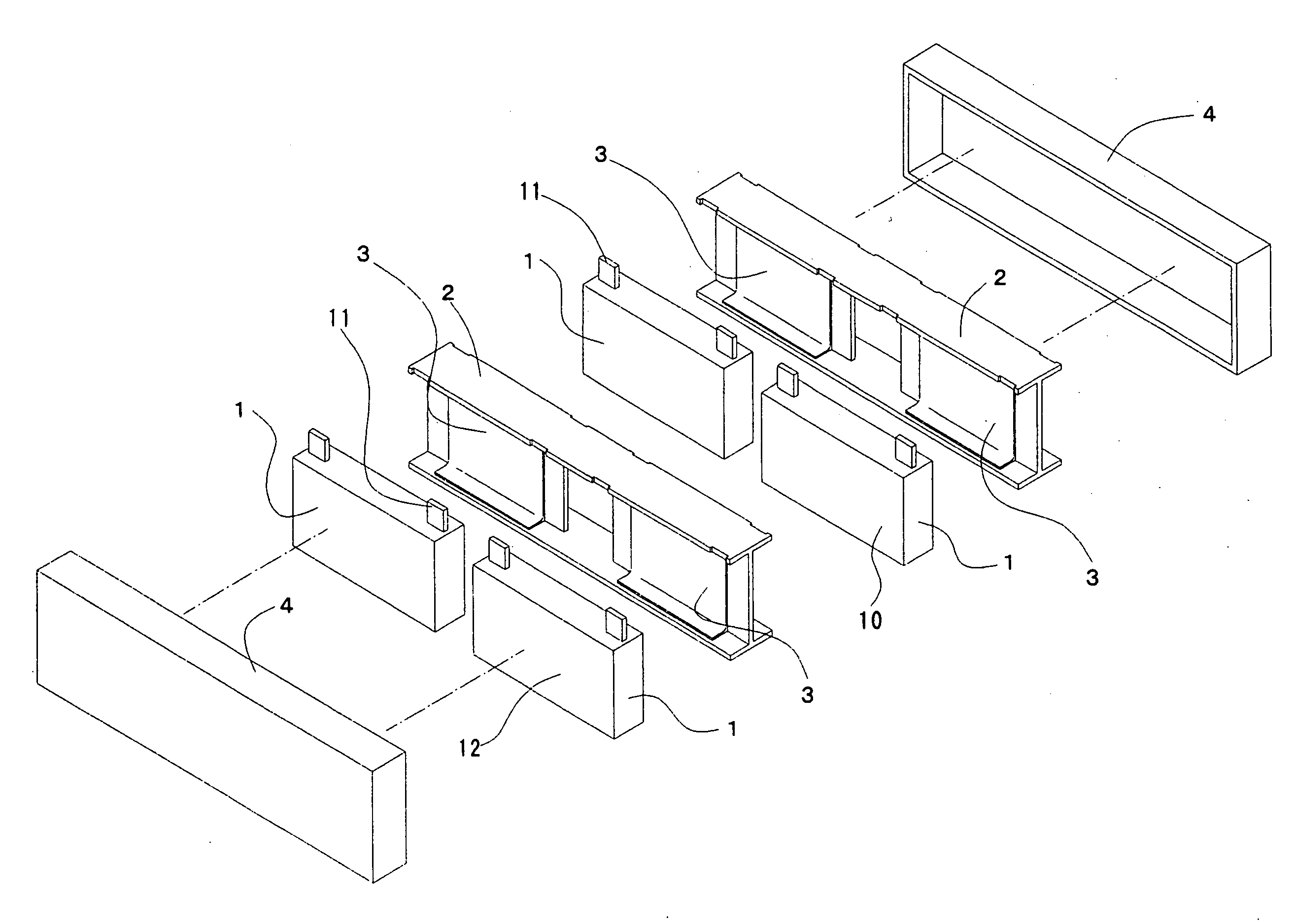
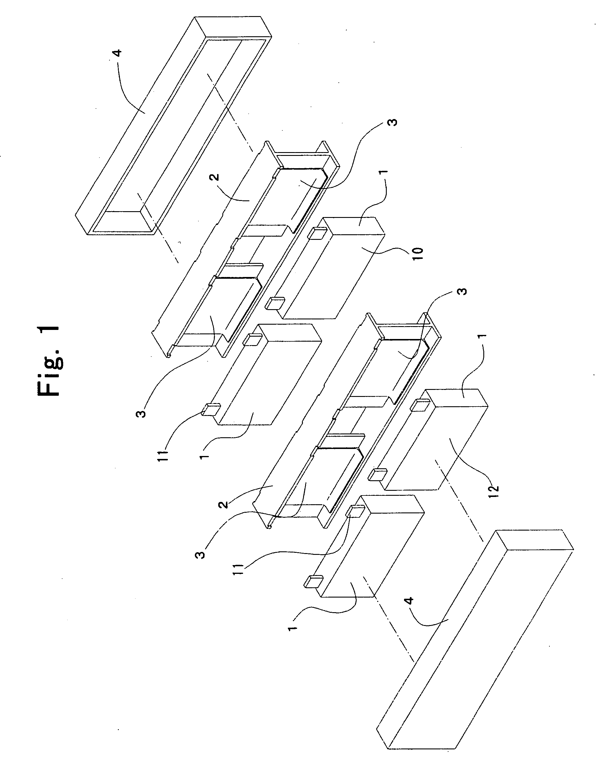
[0052]FIG. 1 illustrates a battery assembly according to Example No. 1 of the present invention in an exploded perspective diagram. The present battery assembly according to Example No. 1 comprises a few dozens of single-battery cells 1, spacers 2, and thermally-conductive members 3. The single-battery cells 1 are formed as a rectangular parallelepiped configuration, and have two largest-area side surfaces 12, respectively. The spacers 2 are made from electrically insulatable resin. A half of the single-battery cells 1 and thermally-conductive members 3 are disposed one after another alternately in a row, thereby making left-side battery subassembly in the drawing. The other half of the single-battery cells 1 and thermally-conductive members 3 are likewise disposed one after another alternately in a row, thereby making right-side battery subassembly in the drawing. The resulting two lines of battery subassemblies, the left-side and right-side battery subassemblies are d...

example no.2

Example No. 2

[0064]As illustrated in FIG. 4, a battery assembly according to Example No. 2 of the present invention comprises the thermally-conductive members 3 that are provided with tabs 34, which protrude from the bases 30 downward into the space 53. Except for this feature, the present battery assembly according to Example No. 2 is constructed in the same manner as the present battery assembly according to Example No. 1.

[0065]The present battery assembly according to Example No. 2 comprises the tabs 34 that make the surface areas of the bases 30 of the thermally-conductive members 3, which are exposed to the space 53, greater. Therefore, the present battery assembly according to Example No. 2 materializes a cooling efficiency, which is upgraded more than that the present battery assembly according to Example No. 1 does.


PUM


Abstract

A battery assembly includes single-battery cells, and thermally-conductive members. The thermally-conductive members are formed of a soft material as a plated configuration. The soft material exhibits thermal conductivity and electric insulatability. The single-battery cells, and the thermally-conductive members are adhered to each other, and are disposed one after another alternately in a row, thereby interposing the thermally-conducive members between the single-cell batteries. The thermally-conductive members include a radiation surface respectively from which heat that the single-battery cells produce radiates. The single-battery cells are cooled indirectly by cooling the radiation surfaces of the thermally-conductive members.

Description

INCORPORATION BY REFERENCE[0001]The present invention is based on Japanese Patent Application No. 2007-219,812, filed on Aug. 27, 2007, the entire contents of which are incorporated herein by reference.BACKGROUND OF THE INVENTION[0002]1. Field of the Invention[0003]The present invention relates to a battery assembly, which can be used suitably as an electric power source for electric vehicles and hybrid vehicles.[0004]2. Description of the Related Art[0005]Nickel-hydrogen secondary battery and lithium ion battery, which are used as an electric power source for driving electric automobile, have been required to exhibit a high energy density, and have been demanded to occupy least on-board space as much as possible. Accordingly, it has been a general practice to make a battery assembly by assembling a plurality of single-battery cells. For example, a few dozens of single-battery cells, which are formed as a rectangular parallelepiped configuration and whose battery capacity is from a ...

Claims


Application Information

Patent Timeline
IPC IPC(8): H01M6/42H01M10/60H01M10/613H01M10/617H01M10/625H01M10/6551H01M10/6555H01M10/6556H01M10/663H01M50/209H01M50/291
CPCH01M2/1077H01M10/5004H01M10/5016H01M10/5032H01M10/5059H01M10/5053H01M10/5055H01M10/5057H01M10/5046H01M10/625H01M10/647H01M10/6556H01M10/6551H01M10/6557H01M10/6555H01M10/6554H01M10/613Y02E60/10H01M50/209H01M50/291
Inventor UCHIDA, YASUNORITSUBAKI, KIMIOTAKEO, SHIGEKIONAKA, HIROSHISUZUKI, TATSUOMITSUI, KENICHI
Owner TOYODA GOSEI CO LTD
Why Eureka
Try Eureka