Mirror Mounting

a technology for mirrors and mounting brackets, applied in the direction of mountings, shafts and bearings, instruments, etc., can solve the problems of increasing the length of the overall assembly of a given length of a mirror, affecting the appearance of the mirror, so as to reduce the length of the overall mirror assembly and increase the overall assembly length. , the effect of increasing the overall assembly length

Inactive Publication Date: 2009-03-05
THE GSI GRP LLC
View PDF0 Cites 15 Cited by
  • Summary
  • Abstract
  • Description
  • Claims
  • Application Information

AI Technical Summary

Benefits of technology

[0007]One of the advantages of the invention is that the mirror can be finished after the mirror has been attached to the disk segment. Prior art mounting systems protrude beyond the plane defined by the reflective surface of the mirror. Such protrusion impedes access to the reflective surface. Consequently, prior art systems mount finished mirrors, which are susceptible to heat and stress caused by the mounting technique. Since the disk segment does not protrude beyond the plane define by the reflective surface of the mirror, the mirror may be processed for stress-relief and the reflective surface may be polished subsequent to mounting on the disk segment. This is particularly advantageous because attaching the mirror to the disk segment before the mirror is finished enables use of attachment techniques that require relatively high heat and other conditions that would be damaging to a finished mirror.
[0008]Another one of the advantages of the invention is that the length of the overall mirror assembly may be reduced. At least some prior art mounting systems utilize a transverse slot which receives the base of the mirror. The strength of the joint formed in the transverse slot is at least in-part a function of slot depth. However, increasing slot depth tends to increase the length of the overall assembly for a mirror of given length. This is problematic because the assembly is cantilevered from the motor, and increasing the length therefore increases susceptibility to vibration. At least one embodiment of the present invention mitigates this problem by securing the mirror to the disk segment on a planar prepared base surface, i.e., without flanges. Use of such a joint is enable because the mirror is mounted prior to finishing, such as by soldering or brazing, which are relatively strong but would possibly damage a finished mirror.

Problems solved by technology

Such protrusion impedes access to the reflective surface.
Consequently, prior art systems mount finished mirrors, which are susceptible to heat and stress caused by the mounting technique.
However, increasing slot depth tends to increase the length of the overall assembly for a mirror of given length.
This is problematic because the assembly is cantilevered from the motor, and increasing the length therefore increases susceptibility to vibration.

Method used


Image

  • Mirror Mounting
  • Mirror Mounting
  • Mirror Mounting

Examples


Embodiment Construction

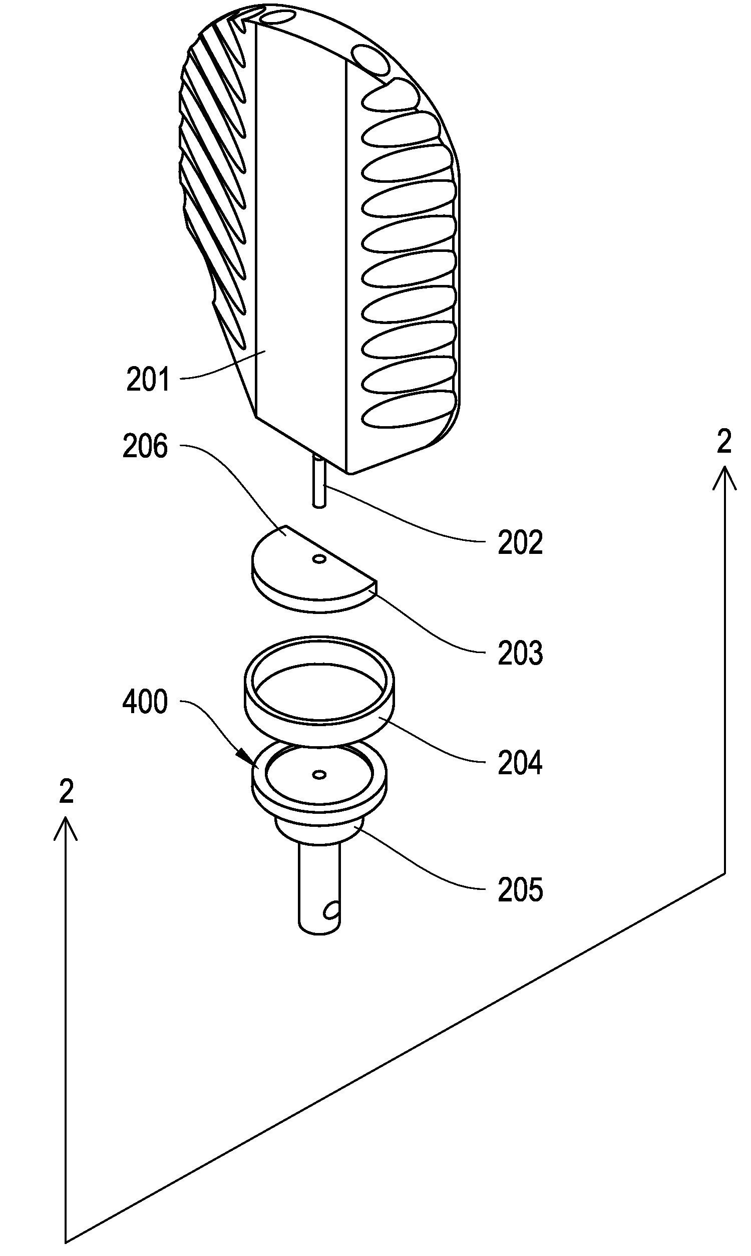
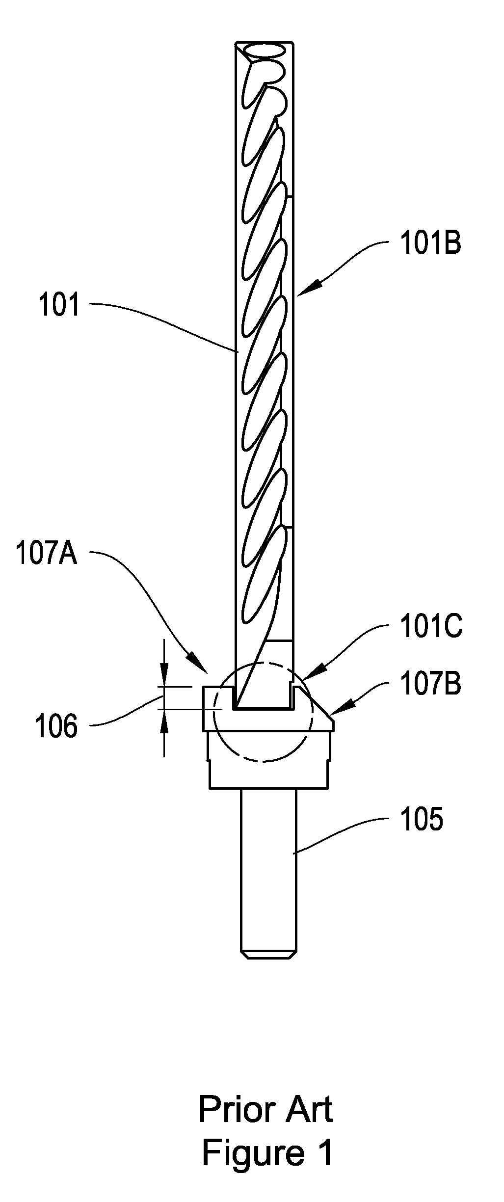
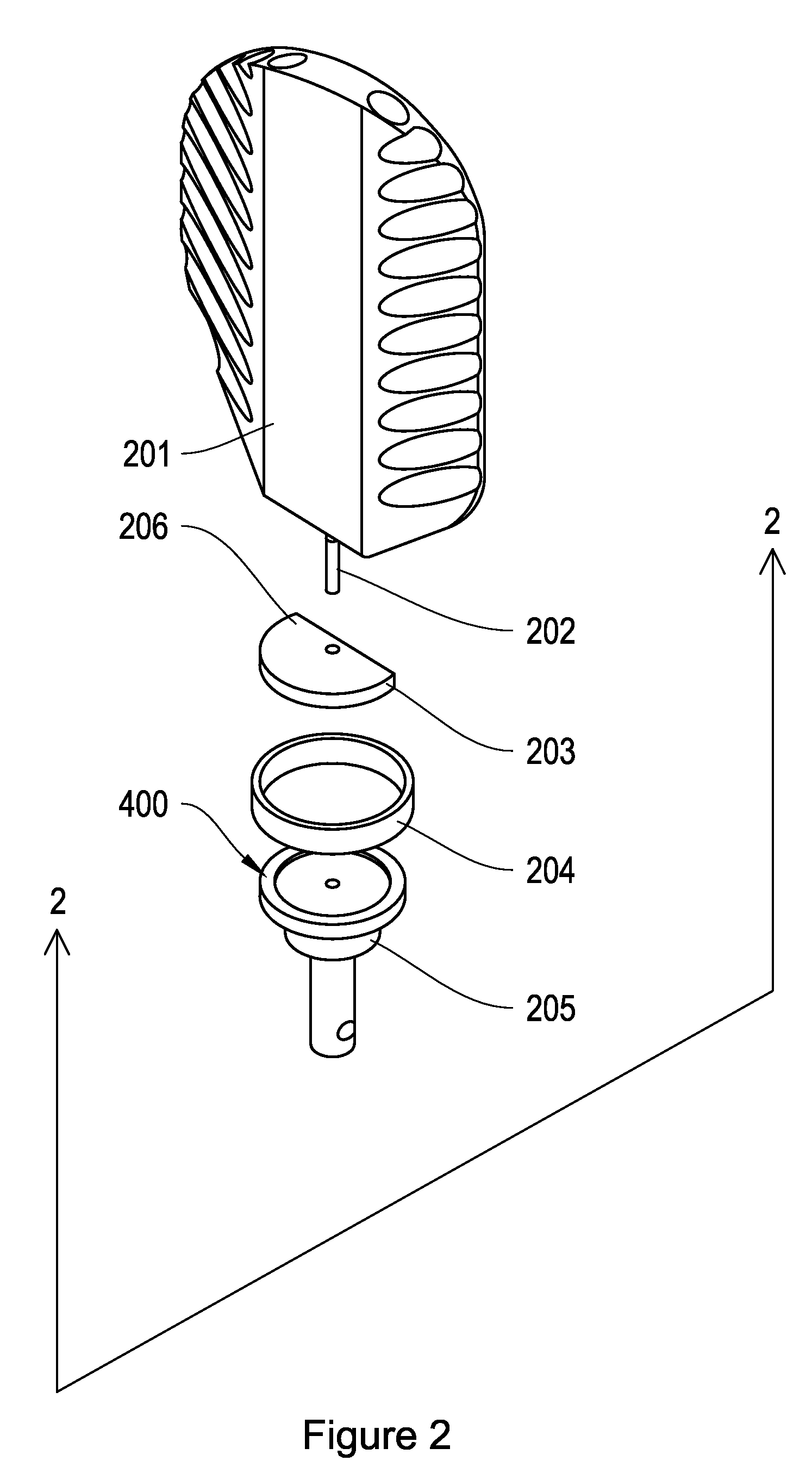
[0015]Referring to FIGS. 1 and 2, in one embodiment of the invention a mirror (201) is coupled to a motor by a disk segment (203), alignment pin (202), clamp ring (204), and shaft coupling (205). Initially, a sub-assembly is made which includes the mirror, alignment pin and disk segment (hereafter, “mirror / disk segment sub-assembly (210)”). The mirror (201) is directly coupled to the disk segment (203). In particular, a prepared planar base surface (301A) of the mirror is bonded to a planar surface of the disk segment by soldering or brazing. The alignment pin (202) is utilized to facilitate alignment of the mirror (201) relative to the disk segment (203). In particular, the alignment pin (202) is inserted into a through-hole formed in the disk segment and also into a half-blind hole in the mirror. The half-blind hole and alignment pin may be of particular depth and length, respectively, that the pin bottoms-out in the half-blind hole, leaving a stub of known length protruding from ...


PUM


Abstract

A disk segment is used to facilitate mounting a mirror to a limited rotation motor. The disk segment has a flat edge which defines a cutaway portion such that, when the flat edge is aligned with the plane defined by the reflective surface of the mirror, the disk segment does not impede access to the reflective surface for polishing and other operations. The disk segment is attached to the mirror before the mirror is finished, thereby enabling use of attachment techniques that would be damaging to a finished mirror. The disk segment may be secured to the motor shaft by various means, including but not limited to a threaded coupling and clamp ring. The coupling may include a tapered shaft or compression fitting in order to facilitate rotational alignment of the mirror relative to the motor. Alternatively, the disk segment may be secured directly to a threaded motor shaft with the clamp ring. Shims may be inserted between the disk segment and threaded motor shaft to achieve a desired rotational alignment of the mirror with respect to the motor.

Description

FIELD OF THE INVENTION[0001]This invention is generally related to mounting structures, and more particularly to mounting structures for lightweight, limited rotation mechanical parts.BACKGROUND OF THE INVENTION[0002]Limited rotation mechanical parts are used in many products. For example, limited rotation oscillatory motors (galvanometers) are used to rotate mirrors in discreet steps to direct light beams in optical scanners. High frequency limited rotation exerts considerable torque on the rotating parts during acceleration and deceleration. Consequently, the rate of rotation is limited by the first torsional resonance frequency of the rotating assembly, which is at least in-part a function of shape and mass. Shape is often constrained by the function of the part, e.g., the required dimensions of the mirror. However, various techniques are known for reducing mass, and thereby increasing the first torsional resonance frequency. For example, a prior art optical scanner as illustrate...

Claims


Application Information

Patent Timeline
Patent Type & Authority Applications(United States)
IPC IPC(8): F16D1/06
CPCF16D1/068G02B7/1821F16D1/0864
Inventor DEBOALT, ROBERT
Owner THE GSI GRP LLC
Why Eureka
Try Eureka