Storage, transporting system and storage set

a transporting system and storage set technology, applied in the field of storage, can solve the problems of high cost of transporting apparatus in storage, time and money for maintenance, etc., and achieve the effect of easy maintenance for each storage, high transporting efficiency and high efficiency

Inactive Publication Date: 2009-03-12
MURATA MASCH LTD
View PDF14 Cites 13 Cited by
  • Summary
  • Abstract
  • Description
  • Claims
  • Application Information

AI Technical Summary

Benefits of technology

[0090]According to the second transporting system with the storage, the system includes the storage set of the present invention described above. Thus it is possible to arrange the storage along a track without the useless space, or effectively. At the same time, in each storage, its keeping efficiency is extremely high and that, its transporting efficiency is also extremely high. Pulling out each storage separately from other storages in the storage set is possible, especially, also doing maintenance for each storage will be easy.
[0091]The effect and other profit in the present invention are clarified from a best mode or embodiments to perform. The best mode or embodiments are described as follows.

Problems solved by technology

2006-049454 and 2003-182815, firstly, there is such a technical problem that the control and the structure of the transporting apparatus in the storage, such as a stacker robot or the like are basically complicated and highly sophisticated, and thus the transporting apparatus in the storage costs high and also costs time and money for its maintenance.
Thus except when the time for maintenance, such a space, between the storages installed along a track, or between the storage and a manufacturing apparatus and the like, becomes useless.
Especially, if the going up and down rack stage is not set at the position for taking-out and putting-in, which is the upper position, it takes a certain time period to move the going up and down rack stage up to the position, Alternatively, it is difficult to take out and put in the load on the going up and down rack stage which is at the lower position.
Therefore it is not possible to transport other load in the storage by use of the going up and down rack stage.
Additionally, in a mechanism for unloading and loading on such a going up and down rack stage, in which a roller or rollers, a belt or belts and a guide or guides and the like are assembled, there is a technical problem that it is basically difficult to unload and load the load and to transport the load in the storage at high speed, while positioning the going up and down rack stage and the load.

Method used


Image

  • Storage, transporting system and storage set
  • Storage, transporting system and storage set
  • Storage, transporting system and storage set

Examples


first embodiment

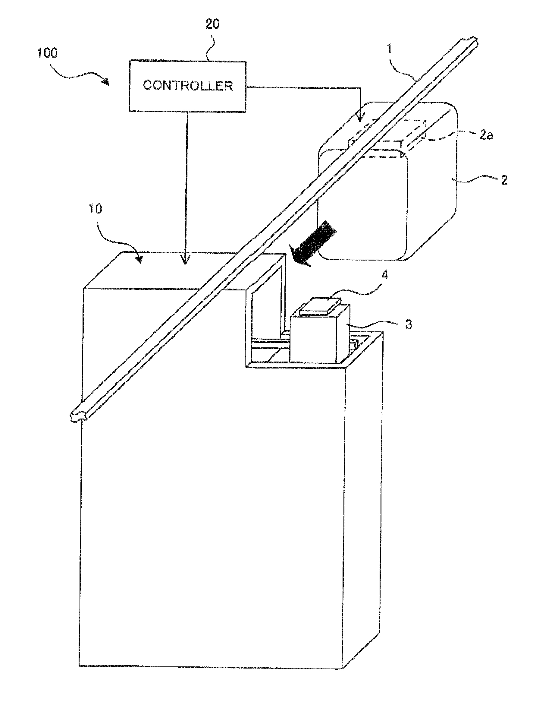
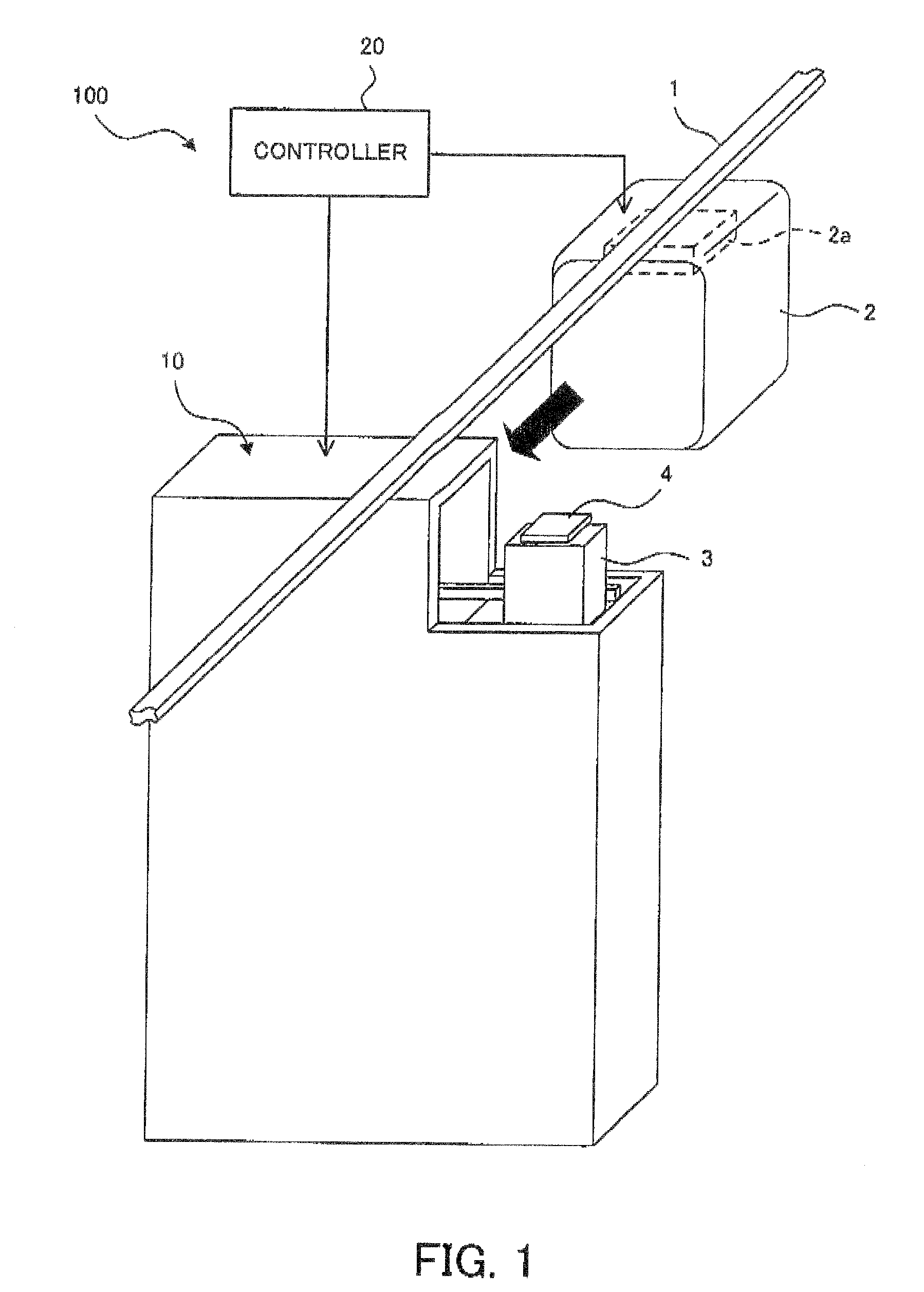
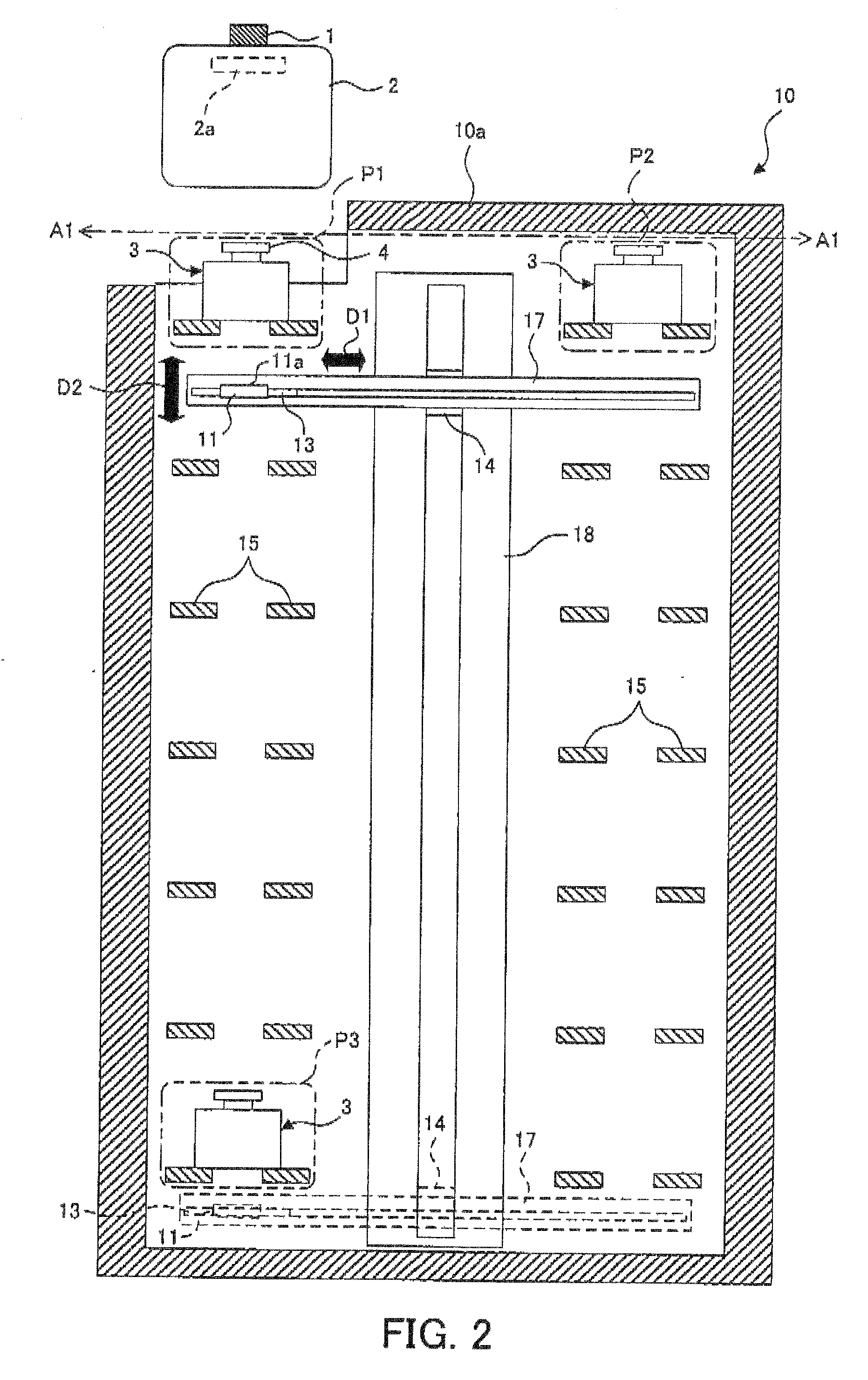
[0103]At first, the structure of the storage in the first embodiment will be explained referring to FIG. 1 to FIG. 3B. FIG. 1 shows an appearance of a transporting system including a storage in the first embodiment, FIG. 2 shows the internal construction of the storage shown in FIG. 1, and each of FIG. 3A and FIG. 3B shows an engagement condition of the first and second putting surfaces in the first embodiment, with respect to a load.

[0104]Especially, the first embodiment is one embodiment of the “first storage” of the present invention.

[0105]In FIG. 1, a transporting system 100 is provided with a rail 1, a transporting carriage 2, a stocker (which is one example of the “storage” of the present invention) and a controller 20. The transporting system 100 drives the transporting carriage 2, and then performs transporting a FOUP 3 on the rail 1. The rail 1, which is an example of the “track” of the present invention, functions as a track for the transporting carriage 2 to travel thereo...

second embodiment

[0130]Next, as the second embodiment in this invention, a modified example of the storage of the first embodiment is explained with referring to FIG. 5. Here, FIG. 5 is a perspective view showing an external appearance of the transporting system provided with the storage of the second embodiment, whose general purpose is the same as that of FIG. 1. In particular, in the storage shown in FIG. 5, a port for unloading and a port for loading are set separately and the horizontal one direction in which the putting portion is moved is disposed in parallel to the track. Incidentally, in the transporting system shown in FIG. 5, the same constitutional elements as those in the transporting system 100 shown in FIG. 1 carry the same reference numerals and the explanations thereof are omitted.

[0131]Especially, the second embodiment is another embodiment of the “first storage” of the present invention.

[0132]In FIG. 5, the transporting system 200 is provided with the rail 1, the transporting carr...

third embodiment

[0143]Next, as the third embodiment in the present invention, the modified example of the arrangement of the storage of the second embodiment is explained. Here, FIG. 7 is a plan view showing the track of the transporting system of the third embodiment. In particular, FIG. 7 is the track to the two ports which the storage of the second embodiment has. Incidentally in the transporting system shown in FIG. 7, the same constitutional elements as those in the transporting system 200 shown in FIG. 5 carry the same reference numerals and the explanations thereof are omitted.

[0144]Especially, the third embodiment is one embodiment of the “second storage” of the present invention.

[0145]In FIG. 7, the transporting system 300 is provided with the rail 1, the transporting carriage 2 and the stocker 40. The transporting system 300 controls the transporting carriage 2 and the stocker 40 by the controller not illustrated to thereby perform the transportation of the FOUP 3 on the rail 1.

[0146]The ...


PUM


Abstract

A storage (10) is provided with a supporting portion (11) capable of supporting a load (3), a horizontal driving portion (13) capable of moving said supporting portion back and forth in a horizontal one direction, a vertical driving portion (14) capable of moving said supporting portion back and forth in a vertical direction, and a rack (15) having a plurality of putting surfaces, each being capable of transferring said load mutually with said supporting portion, said putting surfaces being disposed at a plurality of stages in the vertical direction to each of which said supporting portion can access by said horizontal driving portion, one or more than one of said putting surfaces being disposed at a horizontal position to which said supporting portion can access by said horizontal driving portion. At least one of said putting surfaces functions as a port for unloading and loading said load.

Description

BACKGROUND OF THE INVENTION[0001]1. Field of the Invention[0002]The present invention relates to a storage such as a stocker for temporarily storing a load (i.e., a transported object or an object), such as a FOUP (Front Opening Unified Pod) for accommodating or housing various substrates for manufacturing semiconductor elements and the like, at the position located close to a track, in a traveling system for transporting the load on the track. Here, the “load” (i.e., the “transported object” or “object”) in the present invention means a products an intermediate product, a part, an article, a work, a partly-finished good, a good or the like (e.g, a semiconductor or LCD device), or means a box or container for containing such a product or the like (e.g, a container containing the semiconductor or LCD device), which has been transported or is to be transported by the transporting carriage. The load may be a carrier for containing an object to be carried such as a FOUP.[0003]2. Descrip...

Claims


Application Information

Patent Timeline
Patent Type & Authority Applications(United States)
IPC IPC(8): A47F5/00
CPCB65G37/02H01L21/67775H01L21/67769B65G2201/0297B65G1/0421H01L21/6773
Inventor MURATA, MASANAOYAMAJI, TAKASHI
Owner MURATA MASCH LTD
Why Eureka
Try Eureka