This helps you quickly interpret patents by identifying the three key elements:
Problems solved by technology
Method used
Benefits of technology
[0045]According to the present invention comprising such a configuration, a push-pull amplifier which is capable of operating with low consumption current, and
Problems solved by technology
In order to solve this problem, the overdrive voltage (Vgs−Vth) for the MOS transistors
Method used
Image
Click on the blue label to locate the original text in one second.
Reading with bidirectional positioning of images and text.
Examples
Example
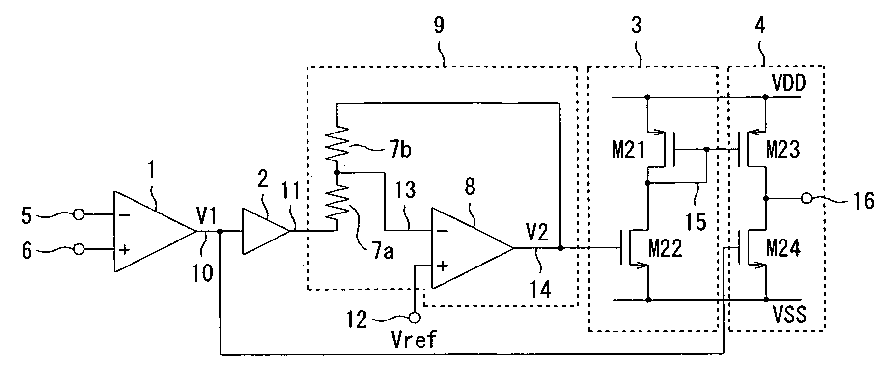
[0054]FIG. 1 is a block diagram illustrating a configuration of a first embodiment of a push-pull amplifier of the present invention.
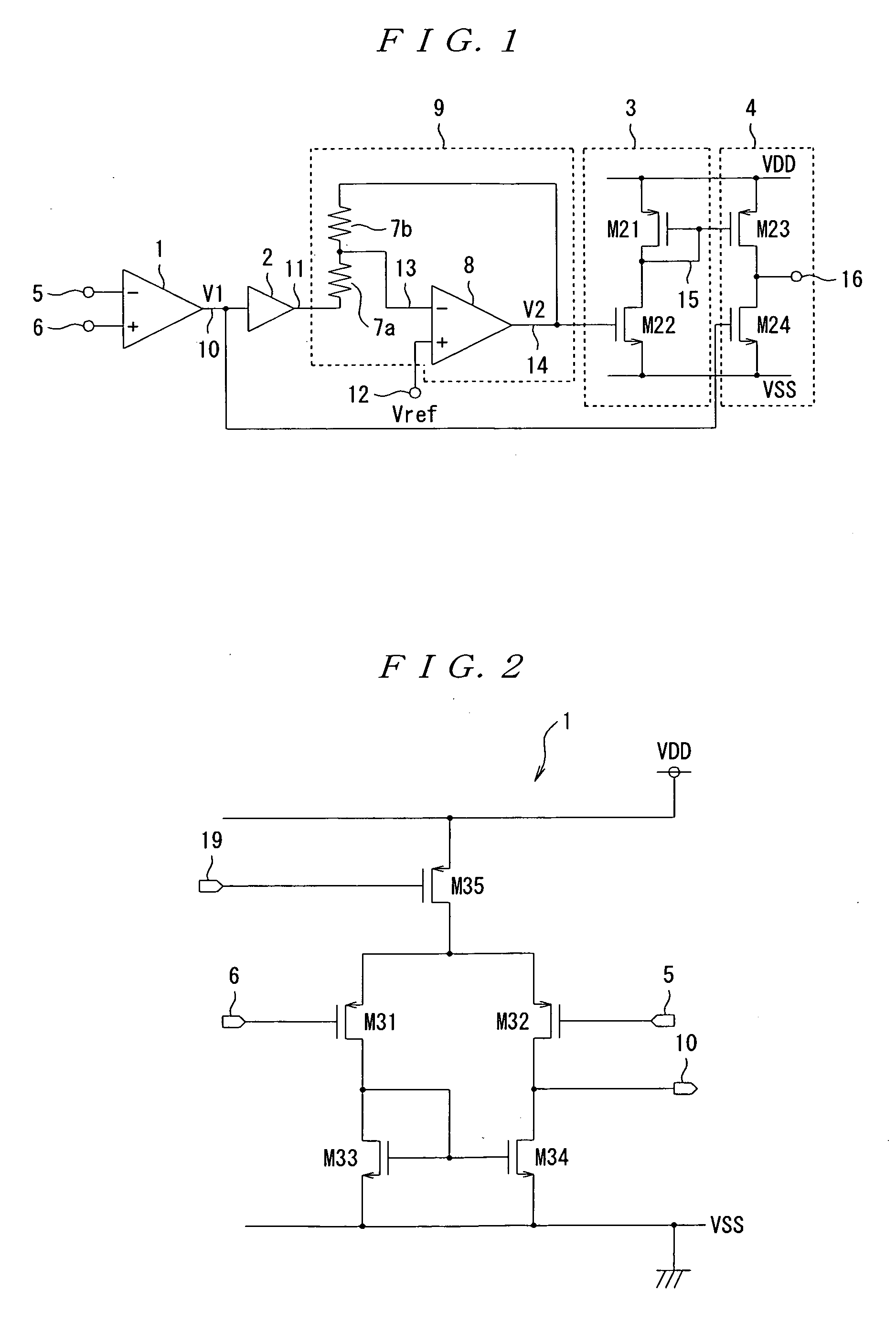
[0055]As shown in FIG. 1, the first embodiment includes a differential amplifier 1; a voltage buffer amplifier 2; a voltage inversion circuit 9 including a set of resistors 7a, 7b and a differential amplifier 8; a level shifting circuit 3 including transistors M21, M22; an output amplifier circuit 4 including transistors M23, M24; an inversion input terminal 5; a non-inversion input terminal 6; an output terminal 16; and a reference voltage terminal 12.
[0056]Generally, the push-pull amplifier is configured as an operational amplifier, having a differential amplifier 1, however, it may lack the differential amplifier 1, or have some other type of amplifier. In this embodiment, the push-pull amplifier having a differential amplifier 1, which is of a type often used in general, will be described.
[0057]The differential amplifier 1 has an inversion input te...
Example
Second Embodiment
[0079]With a push-pull amplifier according to the first embodiment as shown in FIG. 1, in the case where the power supply voltage fluctuation, the ambient temperature fluctuation, and further the manufacturing process fluctuation are not so large, the current at no load flowing in the output transistor can be set in the vicinity of a certain design value. However, in the case where the above-mentioned fluctuations are large, the current at no load flowing in the output transistor will greatly fluctuate.
[0080]Then, by using a circuit as shown in FIG. 7, a push-pull amplifier according to a second embodiment has been adapted to be capable of rendering constant the consumption current at no load constant, independently of the power supply voltage, the manufacturing process, and the ambient temperature.
[0081]In other words, the second embodiment is based on the configuration of the first embodiment as shown in FIG. 1, adding thereto a reference voltage generator circuit...
PUM
Abstract
A push-pull amplifier is provided which, without depending on the overdrive voltage, can increase the peak value of the gate voltage for the output transistor to a level still higher than the conventional one, and is capable of producing an output current with low consumption current that is higher than that available with conventional push-pull amplifiers. The present invention includes a differential amplifier 1, a voltage buffer amplifier 2, a voltage inversion circuit 9, a level shifting circuit 3, and an output amplifier circuit 4. The voltage inversion circuit 9 uses an output of the differential amplifier 1 as an input signal, and includes a set of resistors 7a, 7b, and a differential amplifier 8 for inverting the polarity of the input signal. The level shifting circuit 3 shifts the level of an output signal of the voltage inversion circuit 9 to a prescribed level, while inverting the polarity of the output signal. The output amplifier circuit 4 includes complementary transistors which are different from each other in polarity, and the transistors are inputted with the above-mentioned input signal and the output signal of the level shifting circuit 3, respectively for carrying out push-pull amplification.
Description
BACKGROUND OF THE INVENTION[0001]1. Field of the Invention[0002]The present invention relates to a push-pull amplifier which operates with low consumption current at no load, and has a high current driving capacity.[0003]2. Description of the Related Art[0004]Up to now, push-pull amplifiers having a great variety of configurations have been proposed, and they find their proper applications, based on the respective purposes, and the requirements for power supply voltage, and the like.[0005]Among them, as the push-pull amplifier which operates at low voltage, the circuit as shown in FIG. 4 is known (referring to Japanese Patent Laid-Open No. 2005-311865). As shown in FIG. 4, this push-pull amplifier includes a differential amplifier circuit 1, a differential difference amplifier circuit 17, a level shifting circuit 3, and an output amplifier circuit 4. Further, this push-pull amplifier includes an inversion input terminal 5, a non-inversion input terminal 6, and an output terminal 16....
Claims
Application Information
Patent Timeline
Application Date:The date an application was filed.
Publication Date:The date a patent or application was officially published.
First Publication Date:The earliest publication date of a patent with the same application number.
Issue Date:Publication date of the patent grant document.
PCT Entry Date:The Entry date of PCT National Phase.
Estimated Expiry Date:The statutory expiry date of a patent right according to the Patent Law, and it is the longest term of protection that the patent right can achieve without the termination of the patent right due to other reasons(Term extension factor has been taken into account ).
Invalid Date:Actual expiry date is based on effective date or publication date of legal transaction data of invalid patent.