Laser processing apparatus and laser processing method, debris collection mechanism and debris collection method, and method for producing display panel

Inactive Publication Date: 2009-03-12
SONY CORP
View PDF35 Cites 29 Cited by
  • Summary
  • Abstract
  • Description
  • Claims
  • Application Information

AI Technical Summary

Benefits of technology

[0028]In the above configuration, debris generated when irradiating a resin film or metal film on a substrate of a display panel with laser light is entrained and collected in a vortex gas flow together with gas near a laser light irradiation area. Accordingly, the debris is assembled near a center of the laser light irradiation area by the vortex gas flow and the debris may be efficiently collected while suppressing scattering of the debris to a periphery. Further, the screening device screens a flow of the debris around the opening to reduce an amount of the debris passing through the opening.
[0029]According to a debris collection mechanism

Problems solved by technology

However, in Method 1, not all debris may be blown off a surface near a processed region, sucked and exhausted, and the remaining debris is virtually spread along a flow.
It is difficult to remove and collect debris even if a sucking

Method used


Image

  • Laser processing apparatus and laser processing method, debris collection mechanism and debris collection method, and method for producing display panel
  • Laser processing apparatus and laser processing method, debris collection mechanism and debris collection method, and method for producing display panel
  • Laser processing apparatus and laser processing method, debris collection mechanism and debris collection method, and method for producing display panel

Examples


Example

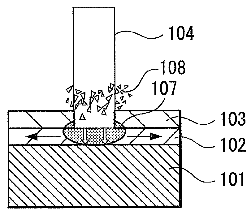
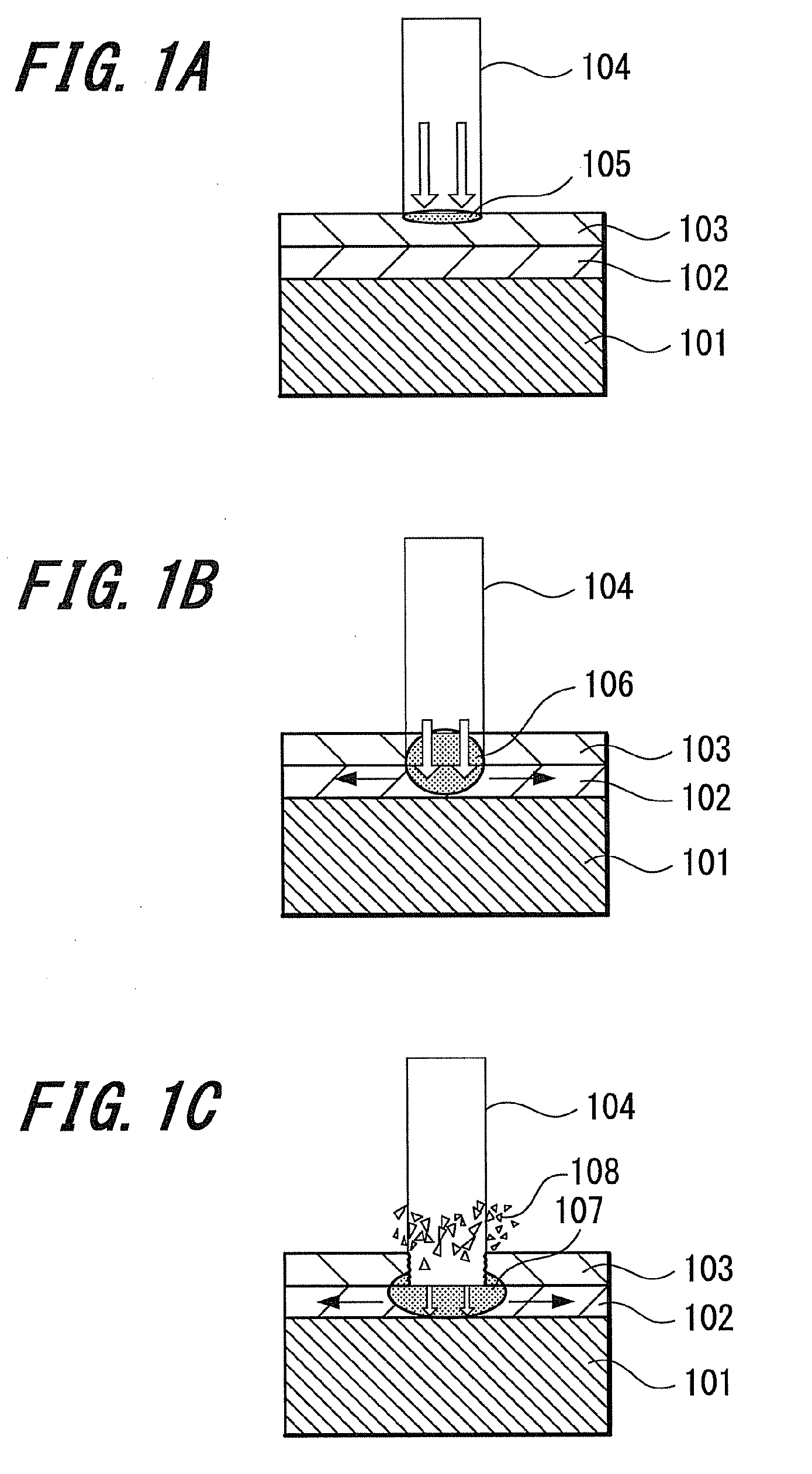
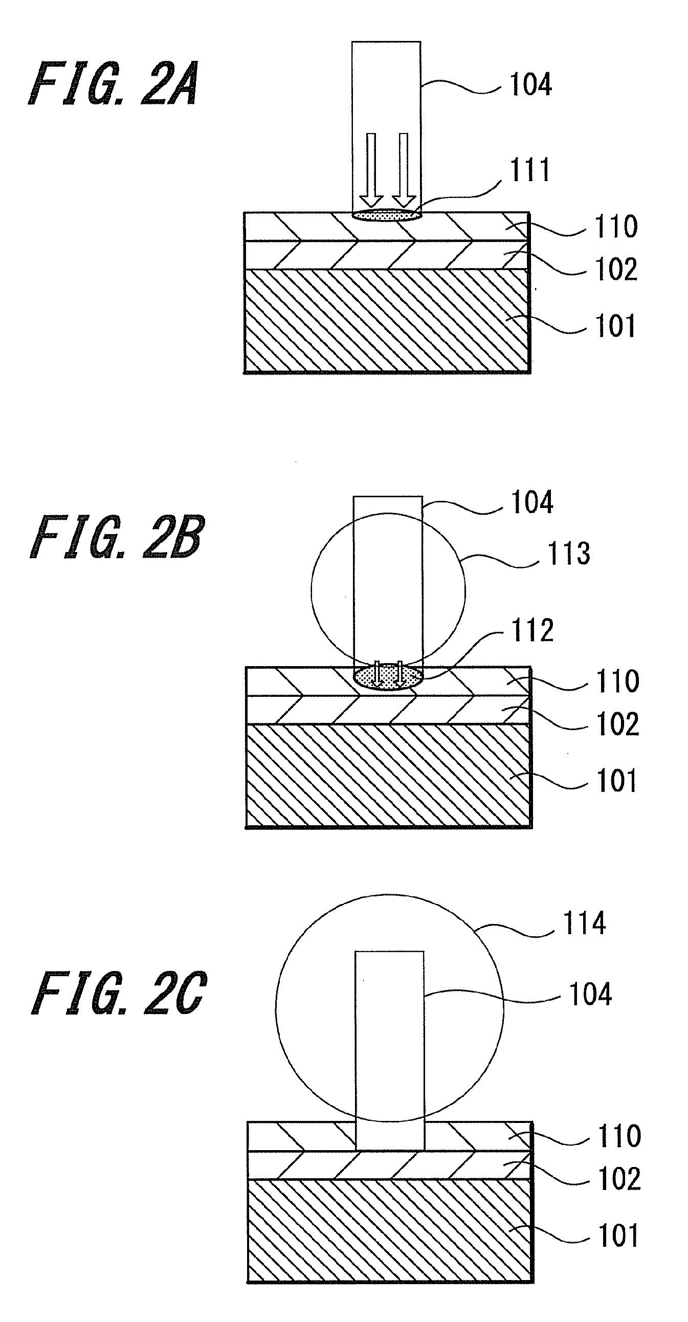
[0052]The present invention provides a laser processing apparatus and a laser processing method and a debris collection mechanism and a debris collection method, which remove and collect debris generated during laser processing by ablation, thermofusion or their mixed action by irradiating with laser light a resin film or metal film (object film) on a multilayer thin film formed on a glass substrate that is an object. In the following description, debris generated during laser processing and before and after being stacked is generally called debris.

[0053]A laser processing apparatus used in an embodiment of the present invention has a laser light source and an optical system optically projecting laser light emitted from the laser light source to a surface of an object with a predetermined pattern, and includes a debris collection mechanism having an opened exhaust hole that is a local exhaust device.

[0054]The debris collection mechanism is placed extremely closer to a resin film or ...


PUM

PropertyMeasurementUnit
Angleaaaaaaaaaa
Sizeaaaaaaaaaa
Widthaaaaaaaaaa

Abstract

A laser processing apparatus is provided for patterning with laser light a resin film or a metal film formed on a substrate. The apparatus includes a laser light source; and a debris collection device having a transmission window through which the laser light is transmitted, a vortex generation mechanism generating a vortex gas flow by allowing gas to flow into a region near a laser light-irradiated area of the resin film or the metal film, and a screening device having an opening through which the incident laser light passes and screening a flow of debris. The mechanism is placed close to the resin film or the metal film on the substrate. Debris generated by laser light irradiation and before and after being stacked on the object film is entrained in the vortex gas flow generated by the vortex generation mechanism and is exhausted to outside through the screening device.

Description

CROSS REFERENCES TO RELATED APPLICATIONS[0001]The present invention contains subject matter related to Japanese Patent Application JP 2007-169381 filed in the Japanese Patent Office on Jun. 27, 2007, the entire contents of which being incorporated herein by reference.BACKGROUND OF THE INVENTION[0002]1. Field of the Invention[0003]The present invention relates to a technology of patterning a resin film or metal film on a multilayer thin film of a flat panel display (FPD) or the like. More particularly, the present invention relates to a laser processing apparatus and a laser processing method, and a debris collection mechanism and a debris collection method, which are intended to remove and collect debris generated during laser processing by ablation, thermofusion or their mixed action by irradiating a surface of an object with laser light, and to a method for producing a display panel.[0004]2. Description of the Related Art[0005]In a process for producing a flat panel display such a...

Claims


Application Information

Patent Timeline
IPC IPC(8): G03F7/20G03B27/32B23K26/00B23K26/142H05K3/00H05K3/08
CPCB23K26/063B23K26/0656B23K26/0732B23K26/123B23K26/1405B23K26/1458H05K2203/082B23K2201/40G02F1/1303G02F1/133371G02F1/133555H05K3/0032H05K3/0038B23K26/409B23K26/1462B23K26/142B23K26/0622B23K26/066B23K26/40B23K2101/40B23K2103/172
Inventor MURASE, HIDEHISASASAKI, YOSHINARIASO, KOSEIYAMADA, NAOKI
Owner SONY CORP
Why Eureka
Try Eureka