Enhanced ultrasound platform

Active Publication Date: 2009-03-12
FUJIFILM SONOSITE
View PDF22 Cites 10 Cited by
  • Summary
  • Abstract
  • Description
  • Claims
  • Application Information

AI Technical Summary

Benefits of technology

[0007]Depending on various needs of embodiments, the exoskeletal member may be made from a rigid material such as a metal or a hard plastic, or from a shock-absorbent material such as a soft plastic or rubber. Differing materials may be chosen based on factors that effect the exoskeletal member's functionality. For example, rigid materials may provide better mechanical support, while shock absorbent materials may provide better impact protection.
[0008]Further, in some embodiments, the exoskeletal member can frame the platform to define angled top and bottom portions. A platform including angled top and/or bottom portions provides a technician-friendly layout and improved ergonomics. For example, an ultrasound platform with an angled bottom portion may be configured to have the bottom portion extend toward the technician and house a user interface. This configuration functions to give a technician more convenient access to a user interface. Further, an ultrasound platform with an angled top portion may be formed such that the top portion extends away from the technician and comprise a handle which allows easy grip and/or movement of the platform. The top portion may additionally or alternatively be configured to hold tools or accessories that may be needed by the technician. In some embodiments the exoskeletal member may be the handle itself. The exoskeletal member may also be used to provide the means or cooperate with the ultrasound platform to hold said tools or accessories.
[0009]In some embodiments, the exoskeletal member provides the

Problems solved by technology

Many current diagnostic and therapeutic ultrasound systems provide cart-based platforms where the display screen, user interface, and control switches are confined to a cart, often in an inconvenient location for a technician.
This configuration forces the technician to twist, turn or reach between the platform and a patient being examined, resulting in a poor ergonomic setup for the technician.
Unfortunately, many times even with these platforms that can be conveniently disposed with respect to the patient, the devices are still not laid out in an ideal ergonomic manner for the technician.
Further, a technician may still need access to various tools and accessories such as a gel bottle, different probe, etc., thereby propagating the poor ergonomic situation.
Another issue occur

Method used


Image

  • Enhanced ultrasound platform
  • Enhanced ultrasound platform
  • Enhanced ultrasound platform

Examples


Embodiment Construction

[0019]It should be noted that the figures that are discussed herein show many different features combined on a single ultrasound platform. This is shown for ease of explanation only, and should not be construed as limiting embodiments of the present invention to containing every feature as shown. One skilled in the art will recognize that different users will have different needs and a platform may be configured accordingly to utilize concepts of the present invention.

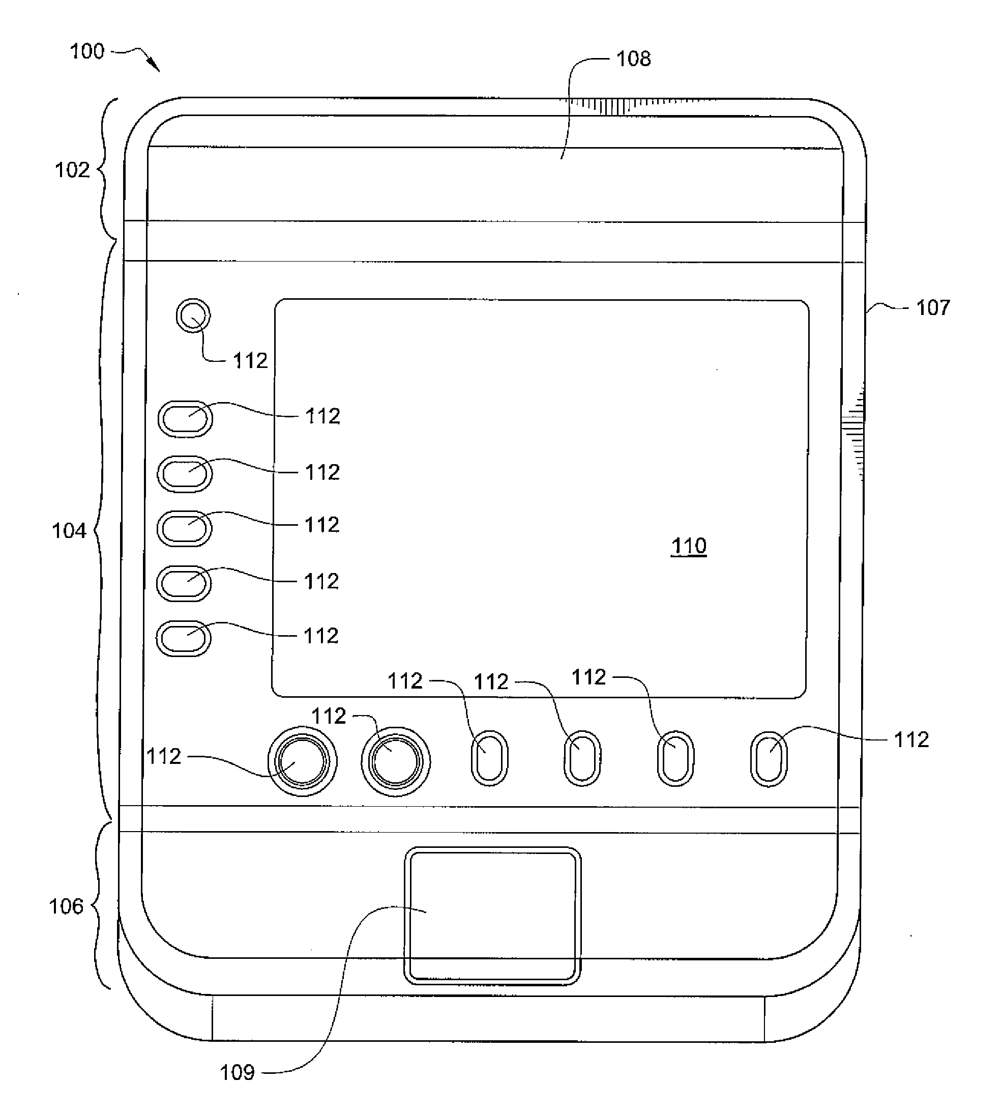
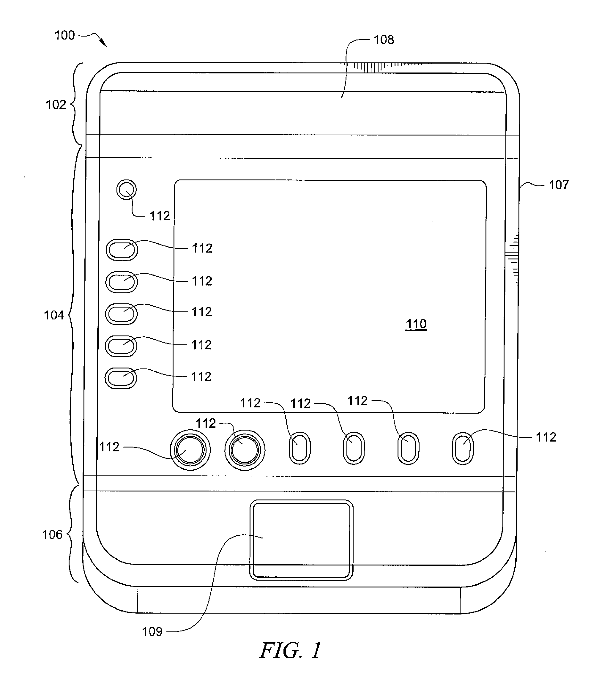
[0020]FIG. 1 shows a front view of an ultrasound platform 100 according to a preferred embodiment of the present invention. Ultrasound platform 100 may be the type of platform used in systems such as ones used in diagnostic and / or therapeutic ultrasound.

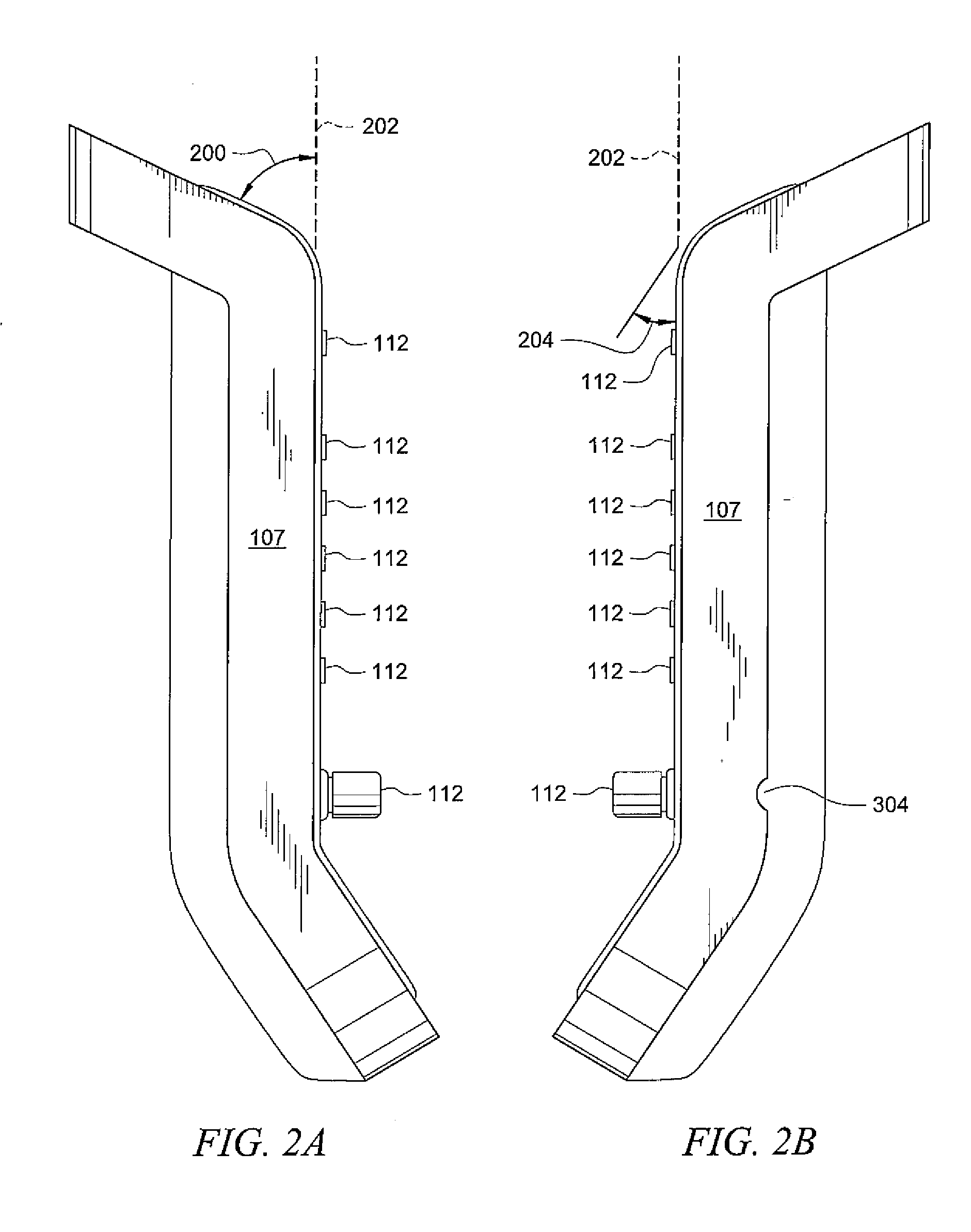
[0021]Platform 100 of the illustrated embodiment has top portion 102, front portion 104, bottom portion 106, and exoskeletal member 107 circumferentially disposed thereon. Exoskeletal member 107 provides for enhanced protection of platform 100 and may also provide the f...


PUM


Abstract

An enhanced ultrasound housing and enhanced ultrasound platform facilitates a technician-friendly layout by providing a beneficial ergonomic layout. Control switches may also be configured to provide convenient implementation of ultrasound techniques. Further, an enhanced ultrasound housing and enhanced ultrasound platform provides physical protection to the device. Physical protection may come in the form of an exoskeletal member, or from a covering which inhibits liquid penetration.

Description

TECHNICAL FIELD[0001]The present application is directed towards ultrasound platforms, and more specifically to providing an ultrasound platform with improved physical protection.BACKGROUND[0002]Many current diagnostic and therapeutic ultrasound systems provide cart-based platforms where the display screen, user interface, and control switches are confined to a cart, often in an inconvenient location for a technician. This configuration forces the technician to twist, turn or reach between the platform and a patient being examined, resulting in a poor ergonomic setup for the technician.[0003]These and other issues have led many ultrasound platform developers to create different platform configurations in an attempt to dispose one or more components of an ultrasound system for more convenient access by the technician. For example, portable platforms or platforms that are attached to an arm which can extend from the system closer to the patient have been developed. These solutions giv...

Claims


Application Information

Patent Timeline
IPC IPC(8): A61N7/00
CPCA61B8/461A61B8/00A61B8/467
Inventor DIENER, ALEXANDER M.SLIGER, BRADLEY J.LORUSSO, TOMVAN EYCK, JERRY J.
Owner FUJIFILM SONOSITE
Why Eureka
Try Eureka