Method for producing piston for internal-combustion engine

a technology of internal combustion engine and manufacturing technique, which is applied in the direction of machines/engines, manufacturing tools, mechanical apparatus, etc., can solve the problems of reducing the flowability of cooling liquid, narrowing the volume of the annular cavity, and time loss and cost, and achieves convenient and efficient production, smooth flow, and easy and well-formed

Active Publication Date: 2009-03-19
RIKEN FORGE +1
View PDF11 Cites 6 Cited by
  • Summary
  • Abstract
  • Description
  • Claims
  • Application Information

AI Technical Summary

Benefits of technology

[0016]According to the present invention, since the crown and the skirt are formed individually; the annular groove for the annular cavity in the inner bottom of the crown and an annular rib in connection with the open edge of the annular groove are formed before the crown and the skirt are joined together; the rib is bent toward the opening of the annular groove by application of pressure to close the opening of the annular groove to thereby form the annular cavity; and the crown and the skirt are joined together, a curled burr is not generated inside the annular cavity, whereby cooling liquid can smoothly flow thereinto. Besides, score lines generated by the formation of the annular cavity do not occur at the top surface and the upper outer circumference surface of the crown, both of which are exposed to high temperature and high pressure, whereby a long-life, high-quality piston for an internal-combustion engine that is less prone to breakage can be produced.
[0017]In addition, since the crown and the skirt are joined together after the annular cavity is formed in the crown, the skirt is out of the way during the formation of the annular cavity, whereby the annular cavity can be readily and well-formed.
[0018]Furthermore, since the rib is bent toward the opening of the annular groove by pressing a pressure roller, the annular cavity having the uniform cross-sectional shape can be efficiently formed entirely around the circumference of the crown.
[0019]Still furthermore, since the crown and the skirt are formed individually; an annular groove for the annular cavity in the inner bottom of the crown and an annular rib in connection with the outer open edge of the annular groove are formed before the crown and the skirt are joined together; the crown and the skirt are joined together; and the rib is pressed inwardly so as to bring the tip of the rib into close contact with the upper outer circumference of the skirt to thereby form the annular cavity, score lines generated by the formation of the annular cavity do not occur at the top surface and the upper outer circumference surface of the crown, which are exposed to high temperature and high pressure, whereby a long-life, high-quality piston for an internal-combustion engine that is less prone to breakage can be readily and efficiently produced.

Problems solved by technology

The annular cavity can be formed in casting using a readily-disintegrative core that is made of sand, however, the operation of forming the core or removing the core from the inside of the casting after the core is disintegrated is not easy, resulting in time loss and cost increase.
However, when the crown is press-welded to the skirt to thereby form an annular cavity therebetween, a curled burr is generated inside the annular cavity due to friction welding, which narrows the volume of the annular cavity.
As a result, flowability of cooling liquid may be lowered, whereby the crown and the skirt of the piston may be burnt or knocking may occur due to overheating of the crown.
In Japanese Unexamined Patent Application Publication No. 2006-46320, since score lines (joint areas between the opening and the rib of the annular groove) may occur during the formation of the annular cavity in the top surface or the upper outer circumference surface of the crown, an inappropriate machining may cause the ejection of cooling liquid in the annular cavity into the combustion chamber through the score lines.
Furthermore, since the top surface and the upper outer circumference surface of the crown are exposed to high temperature and high pressure, high concentrations of stresses may occur at the score lines due to high temperature and high pressure, resulting in breakage of the piston.

Method used


Image

  • Method for producing piston for internal-combustion engine
  • Method for producing piston for internal-combustion engine
  • Method for producing piston for internal-combustion engine

Examples


example 1

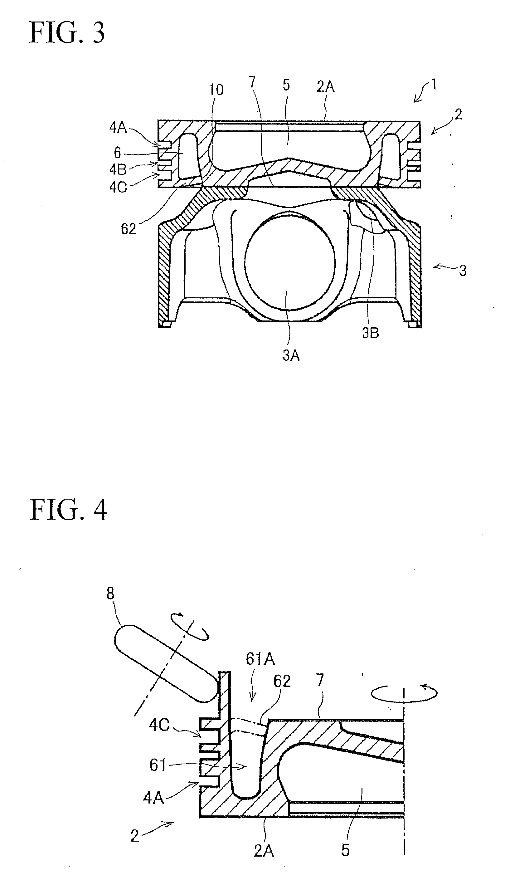
[0033]A method for producing the above-described piston will now be described. First, as in the above description, the crown 2 and the skirt 3 are formed individually. In particular, an annular groove 61 shown in FIG. 4 is formed in the inner bottom of the crown 2 before the crown 2 and the skirt 3 are joined. In addition, an annular rib 62 is formed in connection with the open edge of the annular groove 61.

[0034]The opening 61A of the annular groove 61 is eventually closed with the rib 62 to thereby form the annular cavity 6. In the case of the crown 2 provided with an unfinished annular cavity 6, the crown 2 can be readily molded without a core that is complicated to form even by casting, and can be readily produced by forging or cutting machining.

[0035]In FIG. 4, the annular groove 61 is formed in the inner bottom (outer circumference of the bottom) of the crown 2 with its bottom open and the rib 62 is formed along the outer open edge of the annular groove 61. However, the rib 62...

example 2

[0039]A modification of the present invention will now be described based on FIG. 6. In this example, the crown 2 and the skirt 3 are formed individually as in Example 1 except that the annular cavity 6 is formed after the crown 2 and the skirt 3 are joined together.

[0040]In other words, the annular groove 61 and the rib 62 are formed in the crown 2 before the crown 2 and the skirt 3 are joined together as in Example 1. More specifically, the annular cavity 61 is formed between the grooves 4A to 4C and the combustion cavity 5 so as to form the annular cavity 6 in the inner bottom of the crown 2, and the annular rib 62 is formed in connection with the outer open edge of the annular groove 61. In this example, as shown in FIG. 6, the crown 2 and the skirt 3 are joined together by pressure welding. The rib 62 which extends perpendicularly downward to the skirt 3 is then pressed inwardly to bring the tip of the rib 62 into close contact with the upper outer circumference (a shoulder por...


PUM

PropertyMeasurementUnit
temperatureaaaaaaaaaa
pressureaaaaaaaaaa

Abstract

A method is provided for producing a piston for an internal-combustion engine of the structure in which a piston body which is composed of a crown having a groove for fitting a piston ring into an outer circumference surface and a skirt in connection with the bottom of the crown is provided with an annular cavity for flowing cooling liquid on an inside of the groove, the method comprising the steps of: forming the crown and the skirt individually; forming an annular groove for the annular cavity in the inner bottom of the crown and an annular rib in connection with the open edge of the annular groove before the crown and the skirt are joined together; bending the rib toward the opening of the annular groove by application of pressure to close the opening of the annular groove to thereby form the annular cavity; and joining the crown and the skirt together.

Description

BACKGROUND OF THE INVENTION[0001]1. Technical Field[0002]The present invention relates to a fabrication technique of a piston for an internal-combustion engine. In particular, the present invention relates to a method for producing a piston for an internal-combustion engine having an annular cavity for flowing cooling liquid (cooling oil) into a crown to be exposed to high temperatures.[0003]Priority is claimed on Japanese Patent Application No. 2007-241175, filed Sep. 18, 2007, the content of which is incorporated herein by reference.[0004]2. Background of the Related Art[0005]In general, a piston for use in an internal combustion such as a diesel engine and a petrol engine is made of an aluminum alloy or iron. In the case of a large size diesel engine, iron forging is preferred to withstand its heavy loads. However, in a piston made of iron, a temperature of a top surface of its crown reaches as high as about 500° C. during operation. Even in the case of a piston made of aluminum,...

Claims


Application Information

Patent Timeline
Patent Type & Authority Applications(United States)
IPC IPC(8): B23P15/10
CPCB23P15/10F02F3/003F02F3/22F16J1/09Y10T29/49256Y10T29/49249Y10T29/49265Y10T29/49252Y10T29/4925B21K1/185
Inventor KONDOH, ATSUSHITANAKA, OSAMUKANAI, SHOJIKOMATSU, TAKAAKI
Owner RIKEN FORGE
Why Eureka
Try Eureka