
Mixing Unit for LP-EGR Condensate Into the Compressor

a compressor and condensate technology, which is applied in the direction of combustion engines, non-fuel substance addition to fuel, feeding systems, etc., can solve the problems of high moisture content of exhaust gas, difficult to permanently remove droplets from the system, and erosion of droplets on the compressor wheel, so as to prevent damage to the compressor wheel

Inactive Publication Date: 2009-03-19
BORGWARNER INC
View PDF17 Cites 44 Cited by
  • Summary
  • Abstract
  • Description
  • Claims
  • Application Information

AI Technical Summary

Benefits of technology

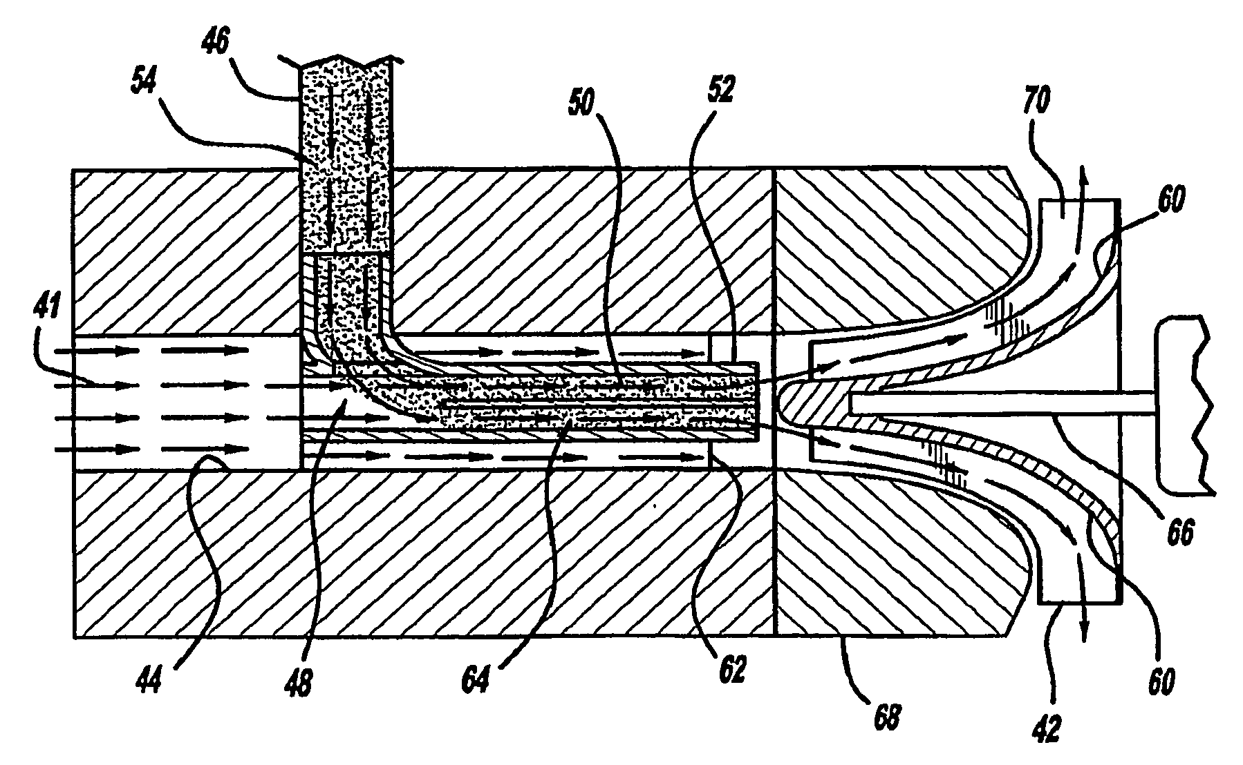
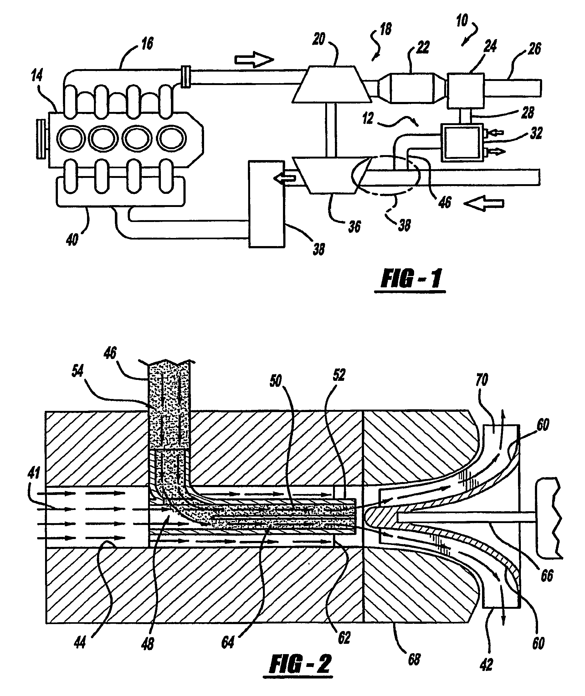
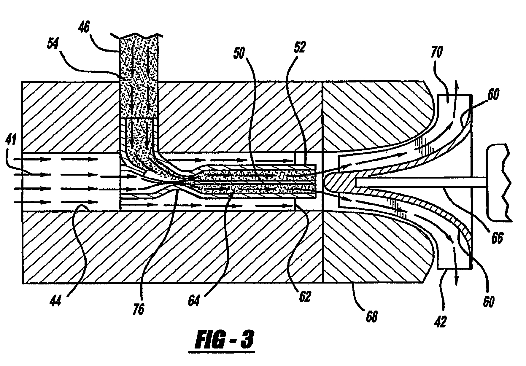
[0009]The present invention is a an EGR system for re-introducing condensate generated in exhaust gas from an engine into a compressor of a turbocharger, having a turbocharger unit having a turbine and a compressor, a low pressure EGR loop located downstream from the turbine and upstream from the compressor, and a compressor wheel located inside the compressor. There is also an intake tube connected to the compressor having an opening to atmosphere for introducing air into the compressor, an EGR-tube connected to the low pressure EGR loop on a first end, and connected to the intake tube on a second end. The present invention also includes a mixing pipe located inside the intake tube for receiving exhaust gas with droplets from the EGR-tube, wherein the EGR-tube delivers the exhaust gas with droplets from the low pressure EGR loop to the mixing pipe, mixing the air and the exhaust gas with droplets forming a mixture containing droplets, and introducing the mixture and the droplets onto the compressor wheel in an area of low circumferential speed, preventing damage to the compressor wheel.

Problems solved by technology

However, exhaust gas may contain a high amount of moisture, dependent on the humidity of the air and the fuel quantity burned in the combustion chamber of the engine.
One major problem with the droplets coming into contact with the compressor wheel is droplet erosion on the compressor wheel.
It is very difficult to permanently remove the droplets out of the system in an area downstream of the compressor because of the negative pressure drop to atmosphere (pumping would be necessary).
This is difficult because the dispersion of droplets can cause damage to the compressor wheel blades.

Method used


Image

  • Mixing Unit for LP-EGR Condensate Into the Compressor
  • Mixing Unit for LP-EGR Condensate Into the Compressor
  • Mixing Unit for LP-EGR Condensate Into the Compressor

Examples


Embodiment Construction

[0015]The following description of the preferred embodiment(s) is merely exemplary in nature and is in no way intended to limit the invention, its application, or uses.

[0016]FIG. 1 is a schematic view of a conventional diesel engine breathing system incorporating the present invention. As will be described herein, a system 10 has a low pressure EGR loop 12. Exhaust gas is generated by an engine 14 and exits through an exhaust manifold 16. The exhaust gas from the exhaust manifold 16 passes through the turbine 20 and is then introduced to a diesel particulate filter (DPF) 22 where the exhaust gas is cleaned of soot material. After going through the DPF 22, the exhaust gas will then flow to an EGR valve module 24 where the exhaust gas is split between either flowing into an exhaust pipe 26 where it leaves the vehicle, or into an EGR path 28 that is part of a low-pressure EGR loop 12 where the exhaust gas will be reintroduced through the engine 14 for combustion.

[0017]The exhaust gas t...


PUM


Abstract

The present invention is a an exhaust gas return system (10) for reintroducing condensate generated in exhaust gas from an engine (14) into a compressor (36) of a turbocharger (18), having a turbocharger unit (18) having a turbine (20) and a compressor (36), and a compressor wheel (42) located inside the compressor (36). The present invention also includes a mixing pipe (52) located inside an intake tube (44) for receiving exhaust gas with droplets (54) from an EGR-tube (46), wherein the EGR-tube (46) delivers the exhaust gas with droplets (54) to the mixing pipe (52), mixing the air (41) and the exhaust gas with droplets (54) forming a mixture (64) containing droplets (50), and introducing the mixture (64) and the droplets (50) onto the compressor wheel (42) in an area of low circumferential speed, preventing damage to the compressor wheel (42).

Description

CROSS-REFERENCE TO RELATED APPLICATIONS[0001]This application claims the benefit of U.S. Provisional Application No. 60 / 762,664, filed Jan. 27, 2006.TECHNICAL FIELD[0002]The present invention relates to an Exhaust Gas Return (EGR) valve assembly used with a turbocharger unit. More particularly, the reintroduction of EGR condensate into the intake pipe in front of the compressor wheel of the turbocharger unit.BACKGROUND OF THE INVENTION[0003]Turbocharging units are a commonly used way to increase the power of an engine, both with conventional internal combustion engines, and Diesel engines. Turbochargers are comprised of a turbine, and a compressor. The turbine receives exhaust gas from the exhaust manifold of the engine, and the turbine wheel located inside the turbine rotates, powering a compressor wheel inside the compressor. The compressor forces high-pressure air into the intake manifold of the engine, increasing power output.[0004]Due to increased environmental concerns, an emp...

Claims


Application Information

Patent Timeline
IPC IPC(8): F02M25/07F02B33/34
CPCF02M25/0709F02M25/0718Y02T10/121F02M25/074F02M25/0722F02M26/06F02M26/15F02M26/19F02M26/35F02B37/00
Inventor JOERGL, VOLKERKIENER, TIMMWEBER, OLAF
Owner BORGWARNER INC
Learn More