Grid type electrostatic separator/collector and method of using same

a technology of electrostatic separator and collector, which is applied in the field of grid-type electrostatic separator/collector and the use of same, can solve the problems of achieve the effects of high percentage of particles being charged, and improving the agglomeration of particles

Inactive Publication Date: 2009-03-19
DUNN JOHN P
View PDF37 Cites 19 Cited by
  • Summary
  • Abstract
  • Description
  • Claims
  • Application Information

AI Technical Summary

Benefits of technology

[0011]The present invention also includes an improved method of charging particles using a pre-charger designed with a narrow air input channel. Using a narrow air input channel into the main air stream increases the probability that entrained particles and generated ions will come in contact, resulting in a high percentage of particles being charged.
[0012]In another embodiment, an external enclosed pre-discharger design and physical arrangement improves agglomeration of sub-micron particles. The present invention also inc

Problems solved by technology

Using a narrow air input channel into the main air stream increases the probability that entrained parti

Method used


Image

  • Grid type electrostatic separator/collector and method of using same
  • Grid type electrostatic separator/collector and method of using same
  • Grid type electrostatic separator/collector and method of using same

Examples


Embodiment Construction

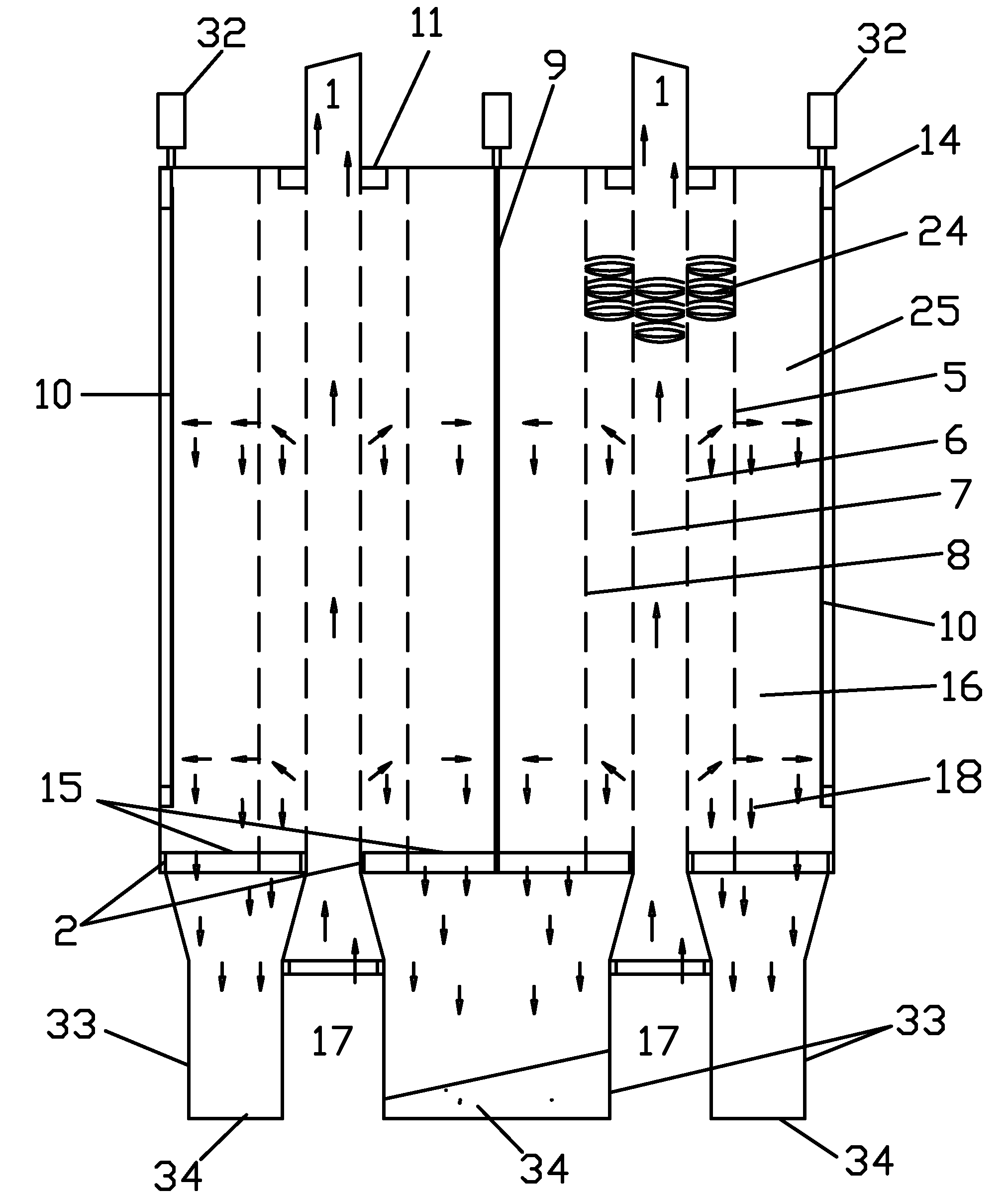
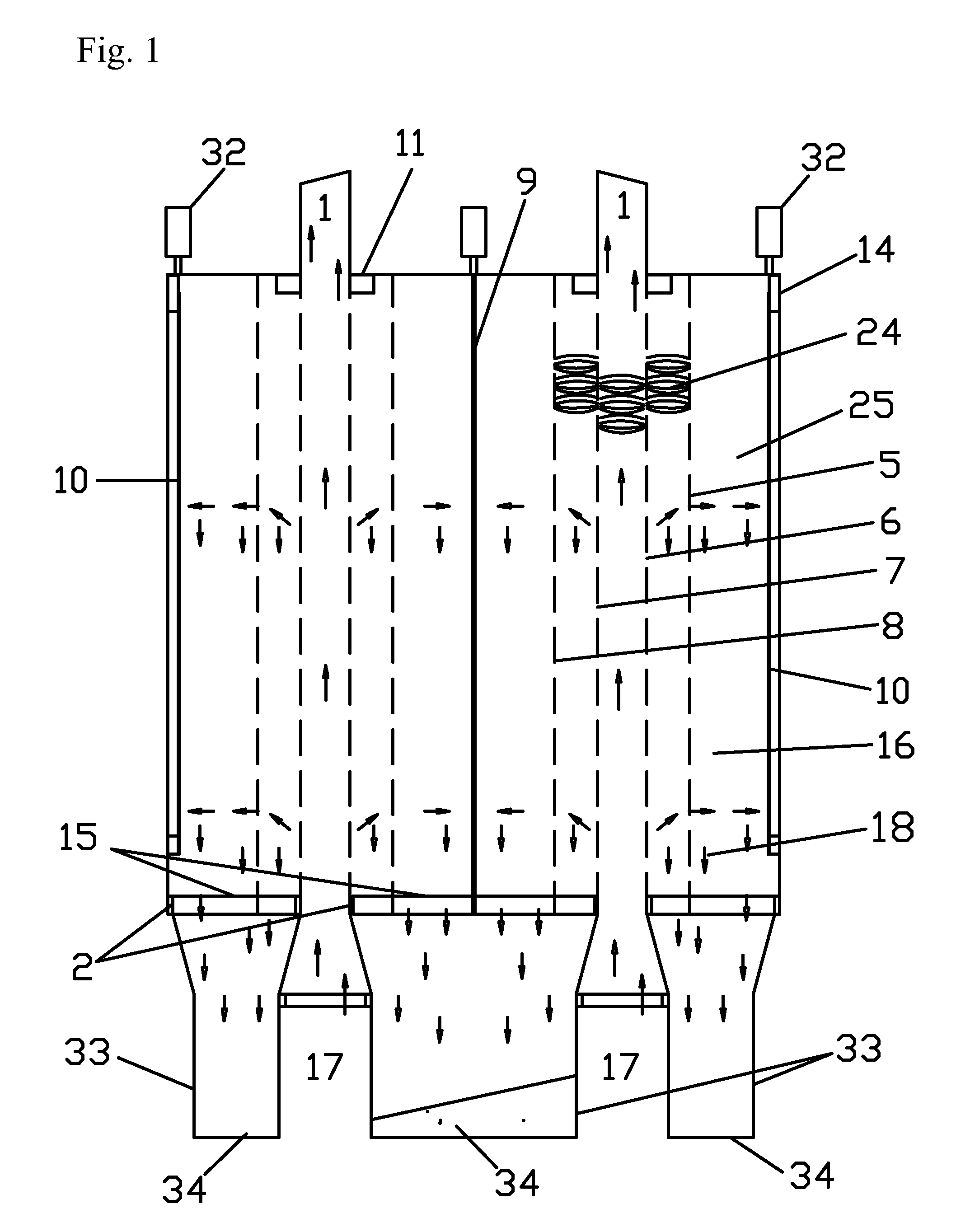
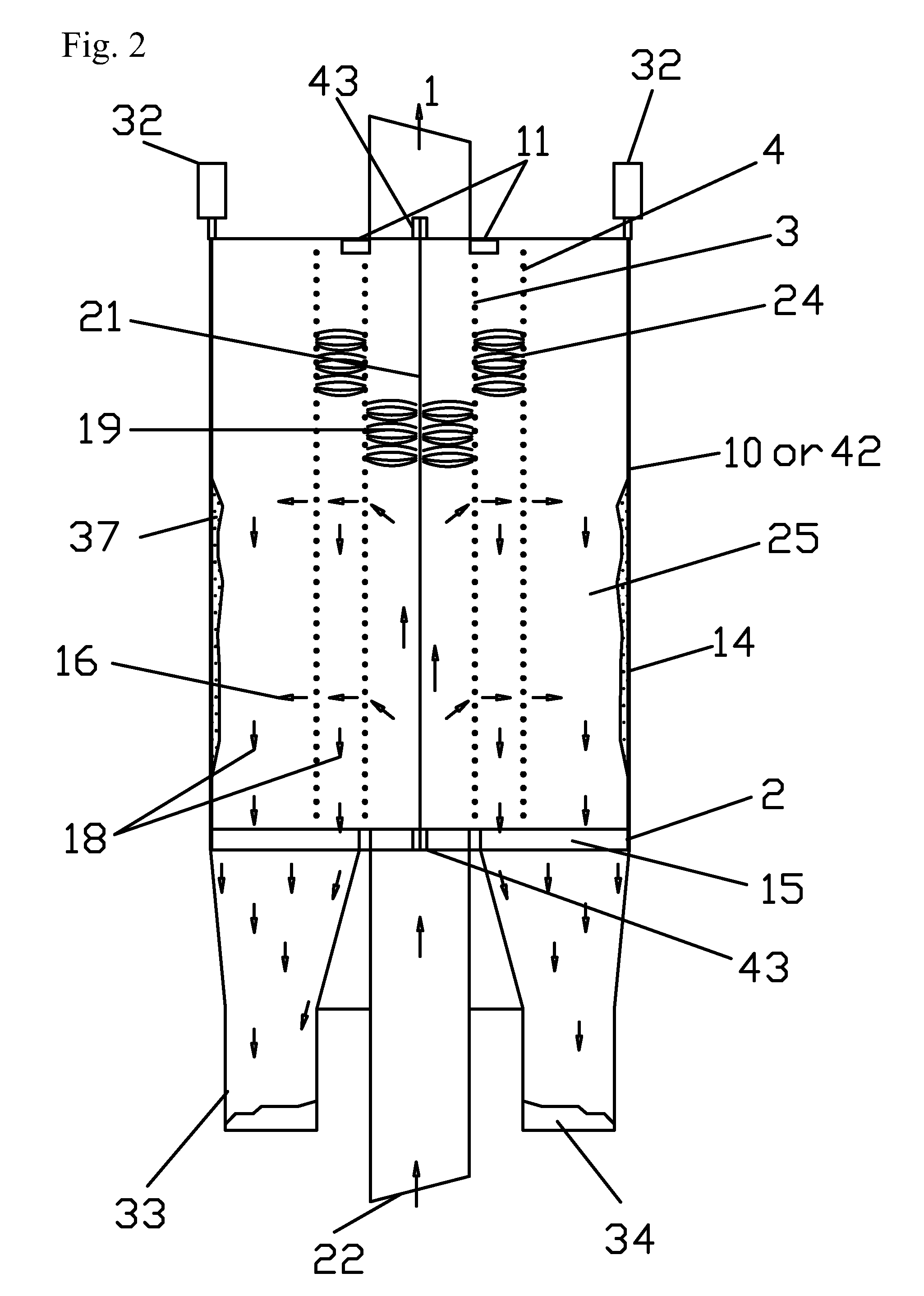
[0027]A grid electrostatic precipitator (GEP) is a dynamic air system where a gradient air flow exists between the center air flow and collecting plate electrodes. External discharge electrodes are designed to charge and then agglomerate the fine particles into larger particles for ease of collection.

[0028]The present invention includes a grid type electrostatic precipitator / collector with a narrow air stream, various external pre-discharger designs with the ability to agglomerate sub-micron particles into larger particles and one or more collection chambers (fields). The pre-chargers preferably include a narrow air input channel. In one embodiment, the collection chamber includes both a recharging zone and a high voltage zone. In another embodiment, at least two collection chambers are placed in series and are separated by agglomerating recharging units. In yet another embodiment, one or more of the collection chambers placed in series includes a recharging zone and a high voltage ...


PUM


Abstract

In one embodiment, apparatuses and methods for collecting particulates use an aperture air flow control system and an inline series of alternating discharge and grid type electrodes each with a separate electrical circuit centrally located between either parallel grid electrodes or plate electrodes. In another embodiment, an external enclosed pre-discharger design and physical arrangement improves agglomeration of sub-micron particles. In yet another embodiment, an external opposing dual channel discharger design also improves agglomeration of particles. In another embodiment, two or more separate electrode arrangements are used within a collecting chamber to improve the operation and collection efficiency of the apparatus. The present invention also preferably increases the frequency of recharging the particles, to increase collection efficiency. In one embodiment, the collection chamber includes both a recharging zone and a high voltage zone followed by a series of fields separated by agglomerating recharging units.

Description

REFERENCE TO RELATED APPLICATIONS[0001]This application claims one or more inventions which were disclosed in Provisional Application No. 60 / 979,206, filed Oct. 11, 2007, entitled “GRID TYPE ELECTROSTATIC SEPARATOR / COLLECTOR AND METHOD OF USING SAME” and Provisional Application No. 61 / 086,274, filed Aug. 5, 2008, entitled “GRID TYPE ELECTROSTATIC SEPARATOR / COLLECTOR AND METHOD OF USING SAME”. The benefit under 35 USC § 119(e) of the United States provisional applications is hereby claimed, and the aforementioned applications are hereby incorporated herein by reference.[0002]This is also a continuation-in-part of co-pending patent application Ser. No. 11 / 380,714, filed Apr. 28, 2006, which is a continuation-in-part of patent application entitled “GRID TYPE ELECTROSTATIC SEPARATOR / COLLECTOR AND METHOD OF USING SAME”, Ser. No. 10 / 872,981, filed Jun. 21, 2004, now U.S. Pat. No. 7,105,041, which is a continuation-in-part of patent application entitled “GRID TYPE ELECTROSTATIC SEPARATOR / C...

Claims


Application Information

Patent Timeline
IPC IPC(8): B03C3/38B03C3/00
CPCB03C3/09B03C3/12B03C2201/30
Inventor DUNN, JOHN P.
Owner DUNN JOHN P
Why Eureka
Try Eureka