Fuel supply apparatuses

a technology of fuel supply and fuel pump, which is applied in the direction of fuel injecting pump, machine/engine, electric control, etc., can solve the problem of unstable idling rotational speed, and achieve the effect of improving pressure adjusting performan

Inactive Publication Date: 2009-03-19
AISAN IND CO LTD
View PDF5 Cites 21 Cited by
  • Summary
  • Abstract
  • Description
  • Claims
  • Application Information

AI Technical Summary

Benefits of technology

[0046]According to the present invention, production of the vapor when the engine is at a high-temperature can be inhibited, and fluctuation of amount of the fuel injected from the injector can be inh

Problems solved by technology

However, for example, when the engine is restarted on a high-temperature condition, vapor may be produced within the fuel due to decrease in the fuel pressure even aft

Method used


Image

  • Fuel supply apparatuses
  • Fuel supply apparatuses
  • Fuel supply apparatuses

Examples


embodiment 1

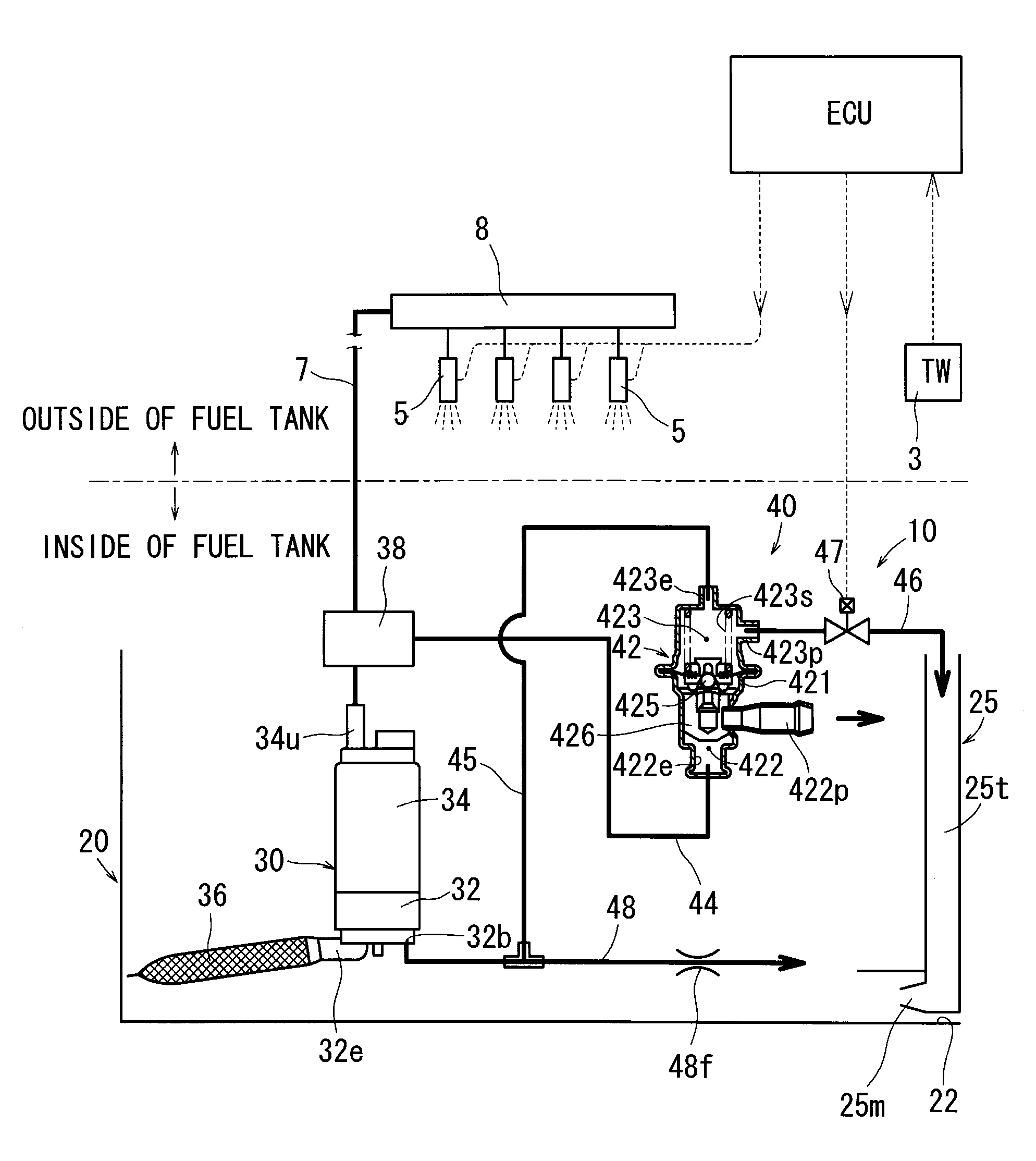
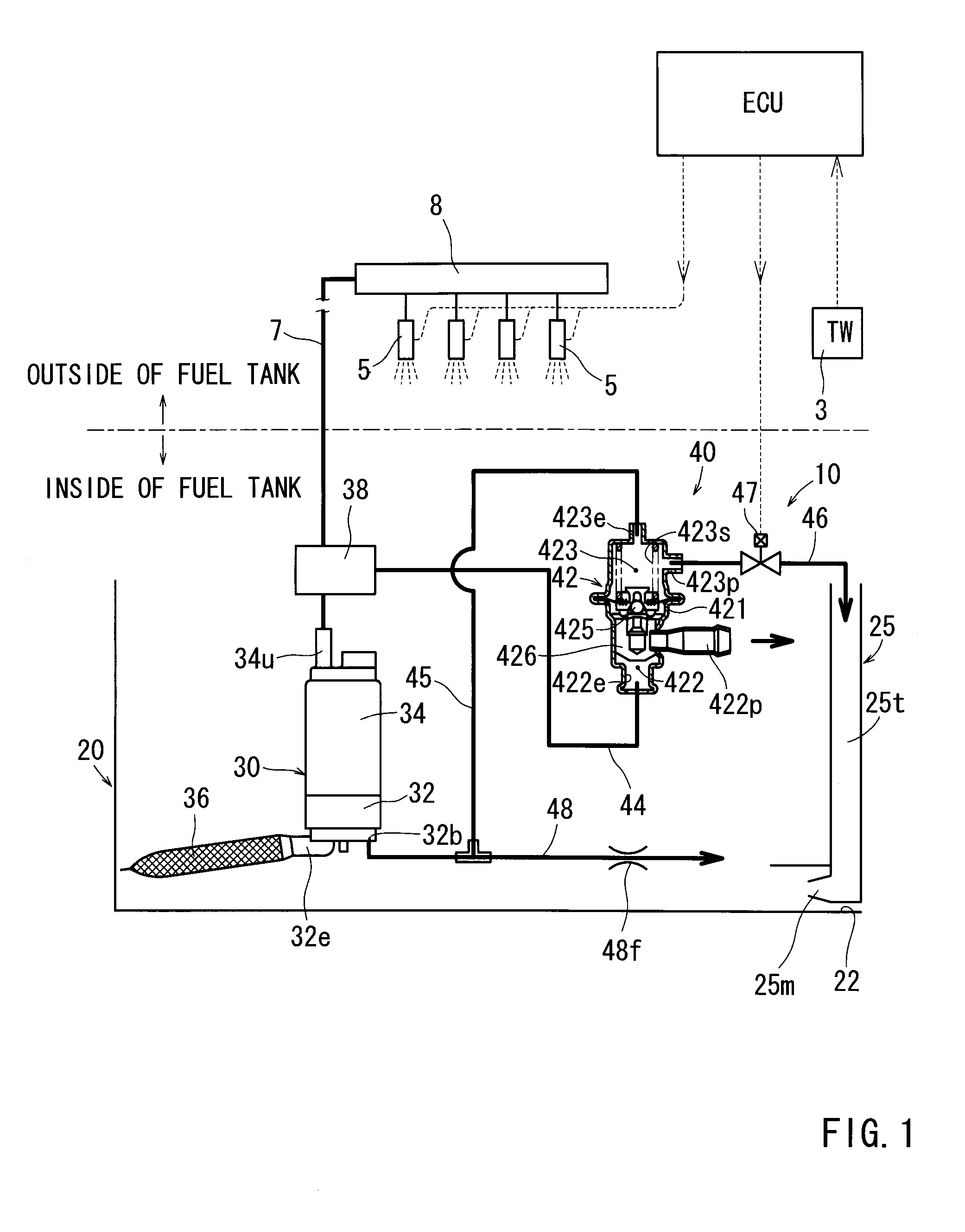
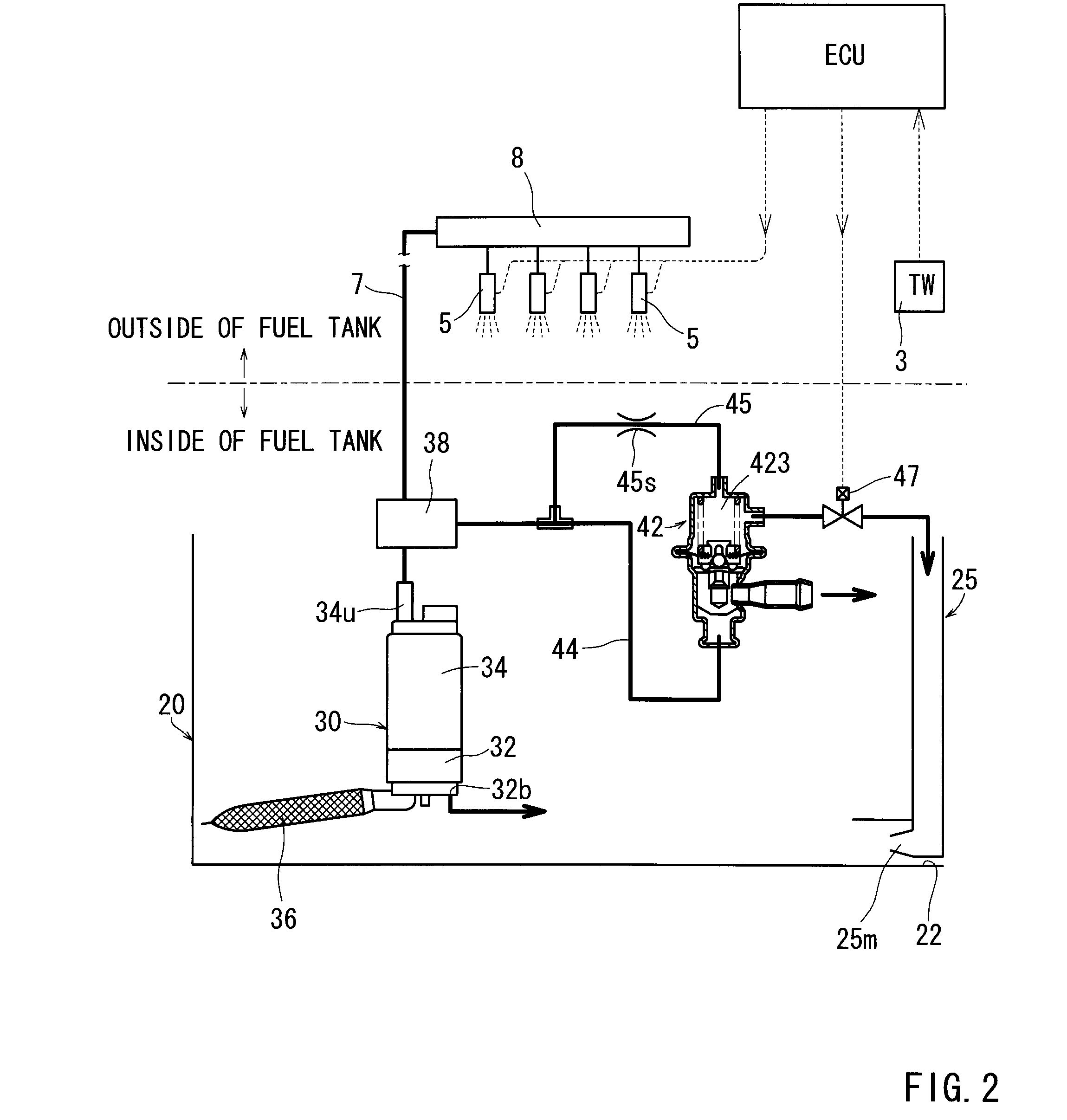
[0088]The fuel supply apparatus according to Embodiment 1 of the present invention will now be described based on FIGS. 1 to 3. The fuel supply apparatus of this embodiment is that mounted to a fuel tank installed mainly on a vehicle, such as an automobile, etc., and a schematic view of the fuel supply apparatus is shown in FIG. 1. FIGS. 2 and 3 show alternative examples of the fuel supply apparatus shown in FIG. 1.

[0089]10>

[0090]The fuel supply apparatus 10 of this embodiment is an apparatus for feeding fuel (not shown) within a fuel tank to injectors 5 (fuel injection valves) of an engine at a predetermined pressure. As shown in FIG. 1, the fuel supply apparatus 10 operates based on a signal from an engine control unit ECU (hereinafter called ECU) and includes a water temperature gauge 3 for measuring a temperature of cooling water of the engine, a reservoir cup 20 configured as a top-open type container located at the bottom within the fuel tank, a fuel pump 30 received within th...

embodiment 2

[0129]A fuel supply apparatus according to Embodiment 2 of the present invention will now be describe based on FIGS. 4 to 11. The fuel supply apparatus of this embodiment is that mounted to a fuel tank installed mainly on a vehicle, such as an automobile, etc., and a schematic view of the fuel supply apparatus is shown in FIG. 4. FIG. 5 is a vertical sectional view showing a pressure adjusting mechanism of the fuel supply apparatus, and FIG. 6 is a vertical sectional view showing a receiving container for receiving the pressure adjusting mechanism, a fuel pump, etc. And, FIGS. 7 to 11 are schematic views showing alternative examples of the fuel supply apparatus, etc.

[0130]10>

[0131]The fuel supply apparatus 10 of this embodiment is an apparatus for pressure-feeding fuel F within a fuel tank T to injectors 5 (fuel injection valves) of an engine. As shown in FIG. 4, the fuel supply apparatus 10 operates based on a signal from an engine control unit ECU (hereinafter called ECU) and incl...


PUM


Abstract

It is an object of the present invention to inhibit production of vapor within fuel when an engine is at a high temperature and to inhibit change of amount of the fuel injected from an injector.
A fuel supply apparatus according to the present invention includes vapor production determining means (3) for determining whether or not the vapor of the fuel is producible, and control means (ECU) for operating a passage resistance adjusting means (47) of a pressure adjusting mechanism (40) to cause increase of the pressure of the fuel supplied to an injector (5) insomuch as the production of the vapor is inhibited when the vapor production determining means (3) has determined a vapor producible condition.

Description

TECHNICAL FIELD[0001]The present invention relates to fuel supply apparatuses that include a fuel pump disposed within a fuel tank, and a pressure adjusting mechanism for adjusting the pressure of fuel discharged from the fuel pump, so that the fuel adjusted in pressure by the pressure adjusting mechanism is supplied to an injector of an engine.BACKGROUND ART[0002]Various apparatuses have been proposed as the above fuel supply apparatuses.[0003]For example, a fuel supply apparatus 100 disclosed in Patent Document 1 includes a fuel tank 101 and a fuel pump 102 disposed within the fuel tank 101 as shown in FIG. 12. Fuel within the fuel tank 101 is pressurized by the fuel pump 102 and passes through a fuel filter 103, and thereafter, its pressure is adjusted to a predetermined pressure by a pressure adjusting mechanism 110, and the fuel is then supplied to each of injectors 105 via a branch pipe section 104. Then, the fuel is injected into each of cylinders (not shown) from each inject...

Claims


Application Information

Patent Timeline
IPC IPC(8): F02M69/54F02M37/04F02M37/20
CPCF02D41/0025F02D41/3836F02D2250/02F02M37/0029F02M2037/228F02M37/0082F02M37/025F02M37/106F02M37/20F02M37/0058F02M37/50
Inventor TAKAGI, KUNIONISHIMURA, KAZUHIKOYONESHIGE, KAZUHIROWADA, SATOMIENDO, HIROKIIKEYA, MASAKI
Owner AISAN IND CO LTD
Why Eureka
Try Eureka