Flow control valve

Active Publication Date: 2009-03-19
SURPASS IND
View PDF11 Cites 33 Cited by
  • Summary
  • Abstract
  • Description
  • Claims
  • Application Information

AI Technical Summary

Benefits of technology

[0054]In this way, the thrust load transmitted to the rotary shaft through the valving element and the threaded portion when the valving element receives the pressure of a fluid is received by the thrust bearing provided on the outside of the motor main body, and the thrust load is released to the motor main body. Therefore, the load applied to the supporting structure of the rotary shaft inside the motor is reduced, and the motor performance can be maintained for a long period of time.
[0055]With the flow control valve according to the present invention, backlas

Problems solved by technology

However, with such a flow control valve, there is a problem in that backlash (chattering) is generated between a male threaded portion provided on the rotary shaft of the motor and a female threaded portion provided on a nut portion that is raised and lowered together with the lifting body and that engages with the male threaded portion, and thus, hysteresis occurs in the flow.
However, with the flow control valve having this configuration, when the rotation of the rotary shaft of the motor exceeds t

Method used


Image

  • Flow control valve
  • Flow control valve
  • Flow control valve

Examples


first embodiment

[0067]A flow control valve according to a first embodiment of the present invention will be described below with reference to the drawings.

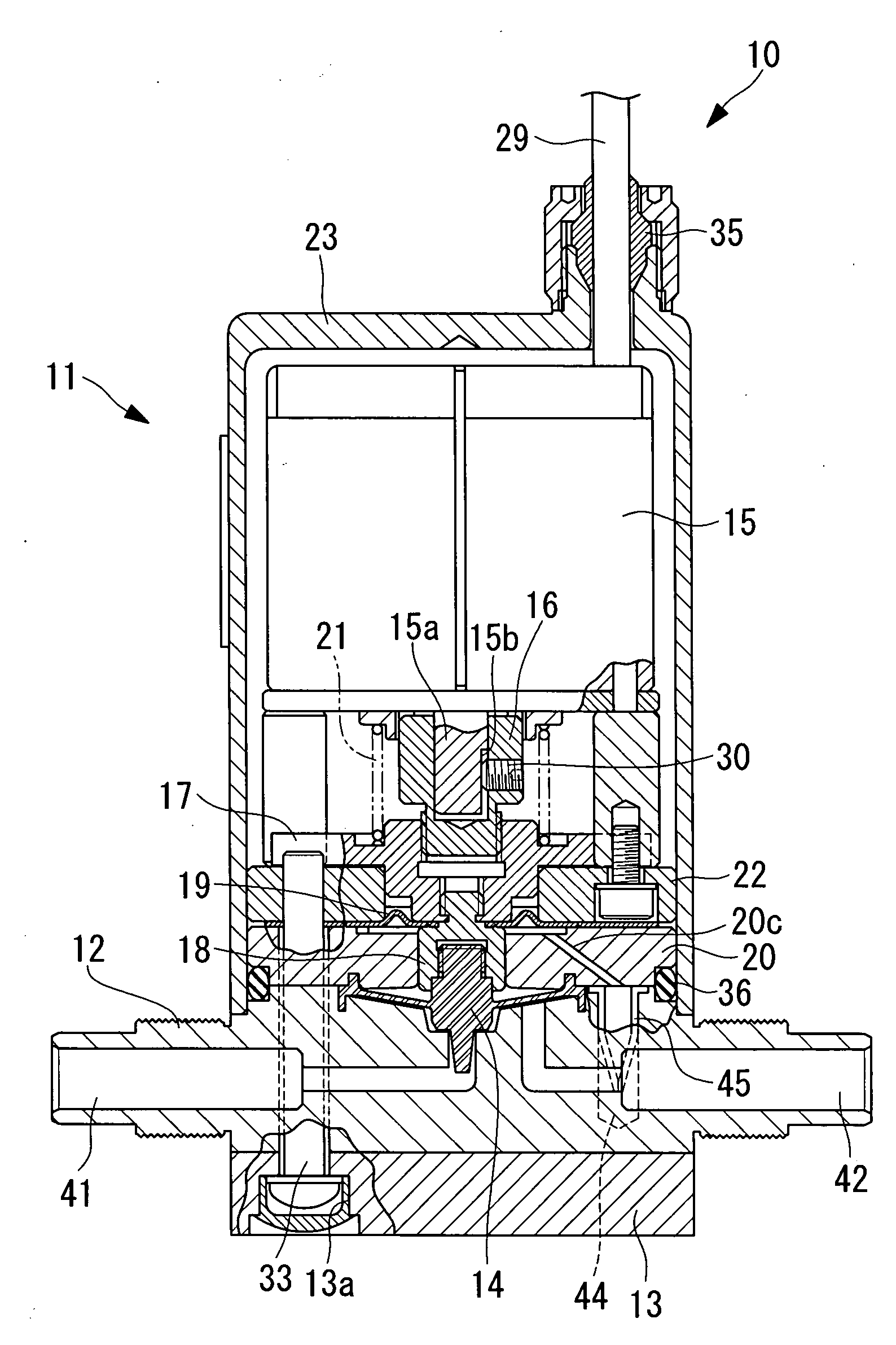
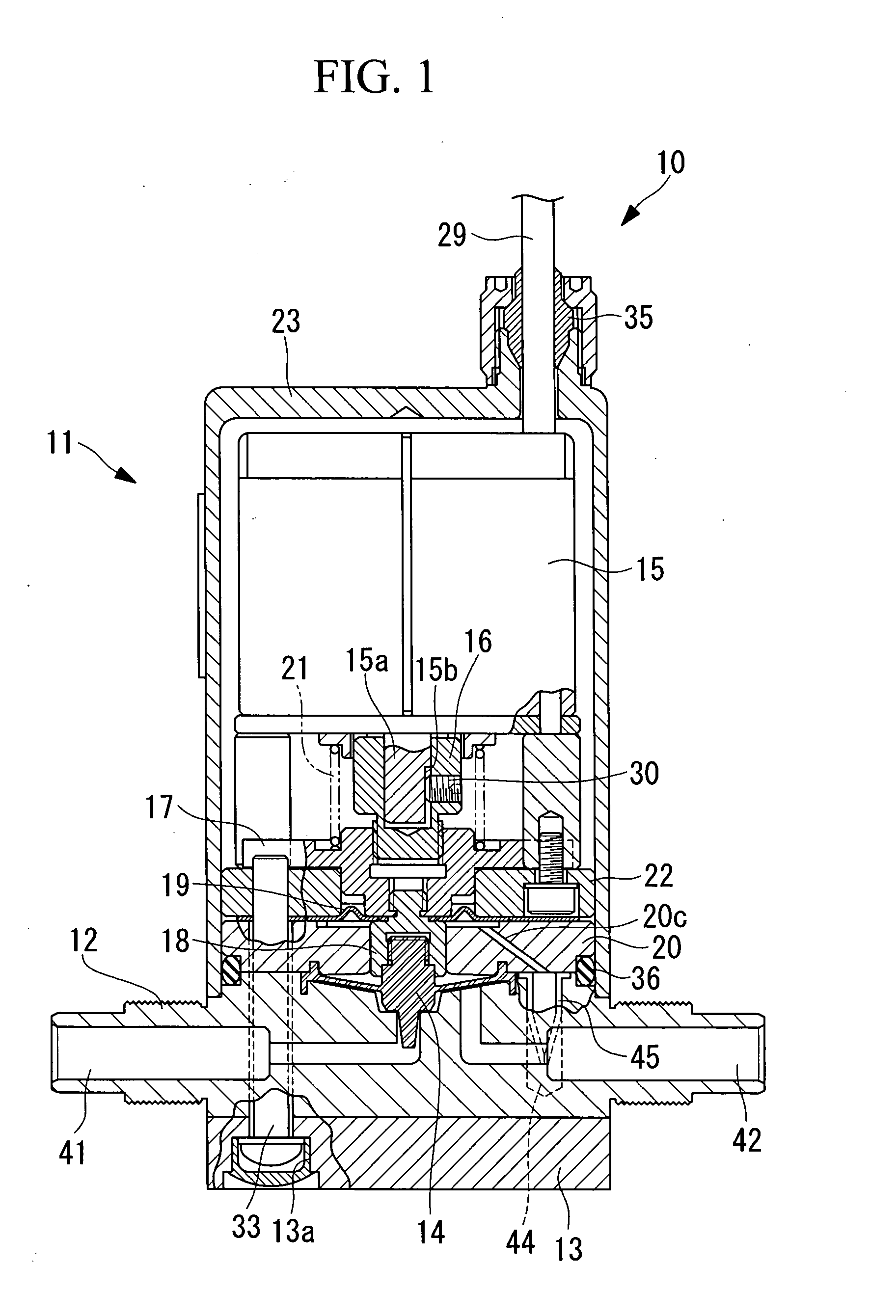
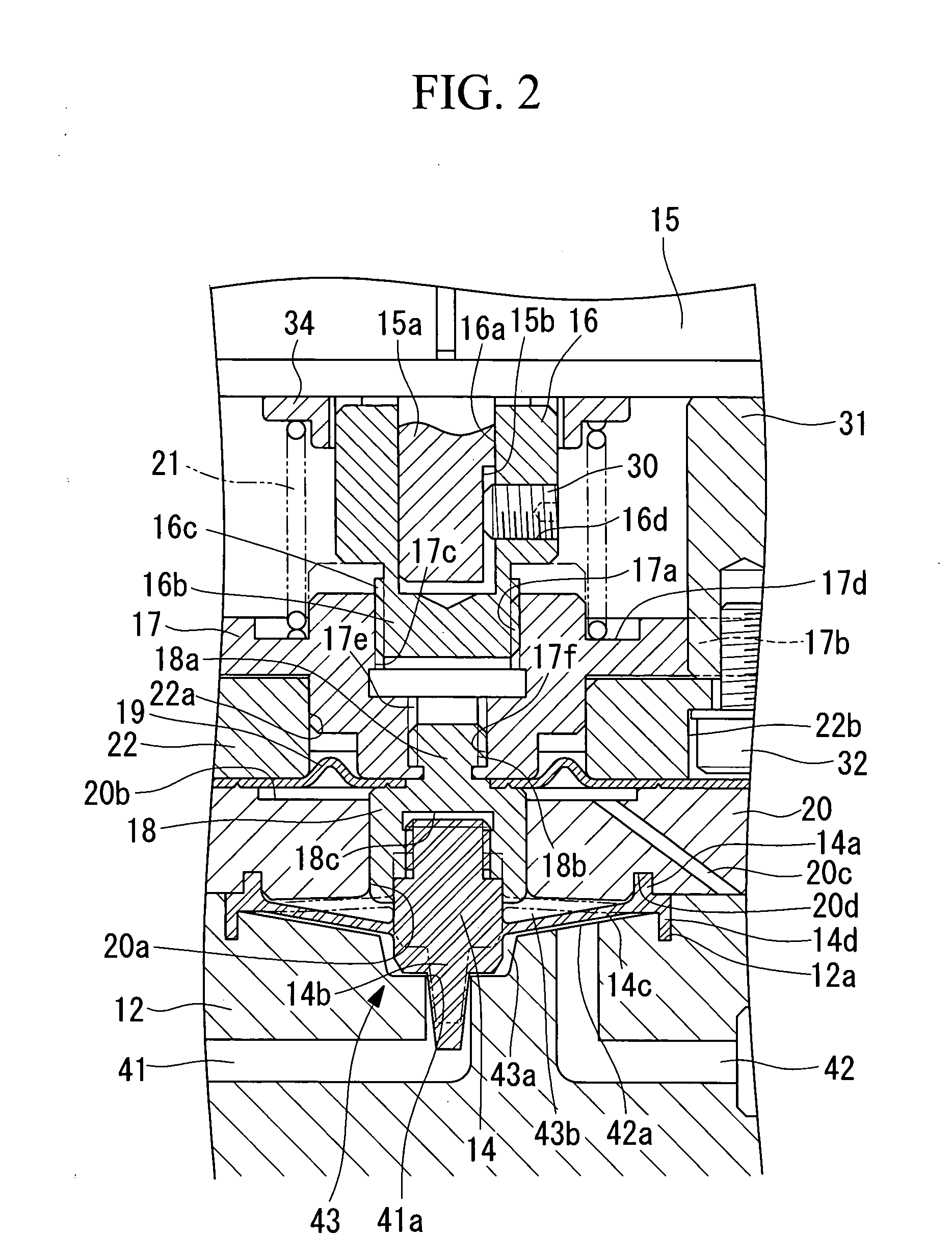
[0068]As shown in FIG. 1, a flow control valve (hereinafter referred to as a “needle valve”) 10 according to this embodiment is mainly constituted of a driven portion 11, a body 12, a base 13, and a diaphragm needle (valving element) 14.

[0069]The driven portion 11 includes a motor 15, a coupling 16, a slider 17, a stopper 18, packing 19, a diaphragm cover 20, a spring (urging member) 21, a cover flange 22, and a cover 23.

[0070]The motor 15 includes, for example, a stepping motor. At the center part of the lower surface of the motor 15, a rotary shaft 15a that protrudes downward and rotates clockwise and counter-clockwise by electrical power supplied via a cable 29. A flat flange surface 15b is provided on part of the rotary shaft 15a. An end surface of a hexagonal socket head screw 30, described below, contacts the flat flange surface 15b.

[0071]...

second embodiment

[0105]A needle valve according to a second embodiment of the present invention will be described with reference to FIG. 3.

[0106]A needle valve 50 differs from the above-described needle valve according to the first embodiment in that a spring 51 is provided instead of the spring 21. Other components are the same as those according to the above-described embodiment. Therefore, descriptions thereof are omitted here.

[0107]The components that are the same as those according to the first embodiment are indicated by the same reference numerals.

[0108]The spring 51 according to this embodiment is a compression coil spring interposed between the slider 17 and the cover flange 22 and constantly urges the slider 17 upward (toward the motor 15). In this way, the backlash between the female threaded portion 17a of the slider 17 and the male threaded portion 16c of the coupling 16 is reduced (or eliminated).

[0109]With the needle valve 50 according to this embodiment, configured as described above...

third embodiment

[0113]A needle valve according to a third embodiment of the present invention will be described with reference to FIGS. 5 and 6.

[0114]A needle valve 60 differs from the needle valve 50 according to the second embodiment in that the structure of the attachment of the motor 15 to the body 12 differs. In the following, the components that are the same as those of the needle valve 50 according to the second embodiment are indicated by the same reference numerals, and detailed descriptions thereof are omitted.

[0115]The needle valve 60 according to this embodiment includes, as a fixing member that fixes the motor 15 to the body 12, a diaphragm cover 70, a cover flange 72, and a housing 81 having structures that differ, in part, from the structures of the diaphragm cover 20, the cover flange 22, and the motor shaft 31, respectively.

[0116]According to this embodiment, a column portion 62 protruding downward coaxially to the rotary shaft 15a from a lower surface 15c is provided at the lower ...


PUM


Abstract

An object is to provide a flow control valve that is capable of reducing or eliminating backlash generated between a male threaded portion and a female threaded portion engaged with the male threaded portion and preventing or eliminating hysteresis in the flow level. The flow control valve includes a body having a fluid inlet and a fluid outlet, a cover attachable to the body, a motor disposed in a space defined by the body and the cover, a valving element connected to a rotary shaft of the motor with a screw member, and an urging member that urges the valving element toward the motor side or toward the side opposite to the motor.

Description

TECHNICAL FIELD[0001]The present invention relates to a flow control valve that controls the flow of a fluid and that is used for fluid transport pipes used in, for example, various industrial fields including chemical plants, semiconductor production, food products, and biotechnology.BACKGROUND ART[0002]There is a known flow control valve that is capable of adjusting the flow of a fluid by rotating, clockwise or counter-clockwise, a rotary shaft of a motor so as to raise or lower a lift body having a push stop piece provided at the lower edge so that the push stop piece squeezes a fluid adjustment tube in the diameter direction or releases the pressure (for example, refer to Patent Document 1).[0003]Patent Document 1:[0004]Japanese Unexamined Patent Application, Publication No. 2004-52797DISCLOSURE OF INVENTION[0005]However, with such a flow control valve, there is a problem in that backlash (chattering) is generated between a male threaded portion provided on the rotary shaft of t...

Claims


Application Information

Patent Timeline
IPC IPC(8): F16K31/04F16K1/32
CPCF16K7/12F16K31/04F16K41/103F16K31/508F16K31/047Y10T137/7882Y10T137/7847
Inventor HASUNUMA, MASAHIROUSHIGUSA, YOSHIHIRO
Owner SURPASS IND
Why Eureka
Try Eureka