Navigation image display apparatus and method thereof

Inactive Publication Date: 2009-03-19
ELITEGROUP COMPUTER SYSTEMS
View PDF7 Cites 5 Cited by
  • Summary
  • Abstract
  • Description
  • Claims
  • Application Information

AI Technical Summary

Benefits of technology

[0008]Therefore, it is one of objectives of the present invention to provide a navigation image display apparatus and method thereof for increasing the effectiveness of display as well as reducing the cost of the navigation image display apparatus.

Problems solved by technology

Such conventional navigation image display apparatus can be realized by using Liquid Crystal Display or Vacuum Fluorescent Display (VFD), however each yields insurmountable drawbacks.
If Liquid Crystal Display is adopted, this would lead to the light deficiency problem, especially while such navigation image display apparatus is applied to HUD, the driver is difficult to identify the navigation image displayed on the windshield glass, which is displayed by navigation image display apparatus in daytime.
However, adopting Vacuum Fluorescent Display to realize dot matrix means would result in the drawback of control circuit design difficulty caused by excess control points.
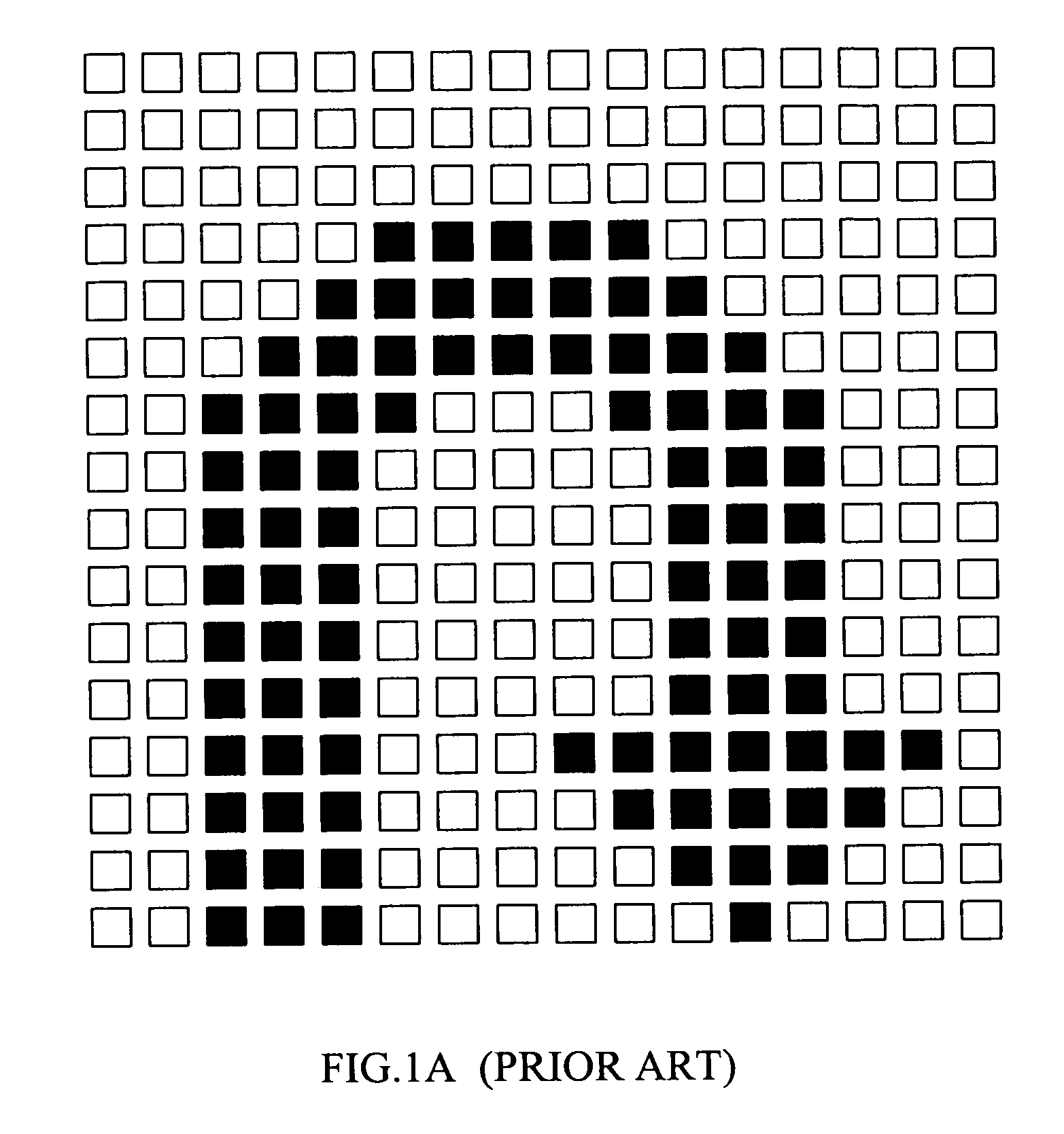
As illustrated in FIG. 1A, the point matrix has 256 control points, thus the control circuit can be realized via wafer implant method, however the cost is high.
If using the method of plug-in control circuit design, the circuit routing trace of the Vacuum Fluorescent Display is deployed on the glass substrate, and the space between traces must be larger than a constant space, hence the trace can not increase unconditionally due to the restriction of space limitation.
Therefore, such a plug-in control circuit design method can not realize a large number of control points within a limited display area.
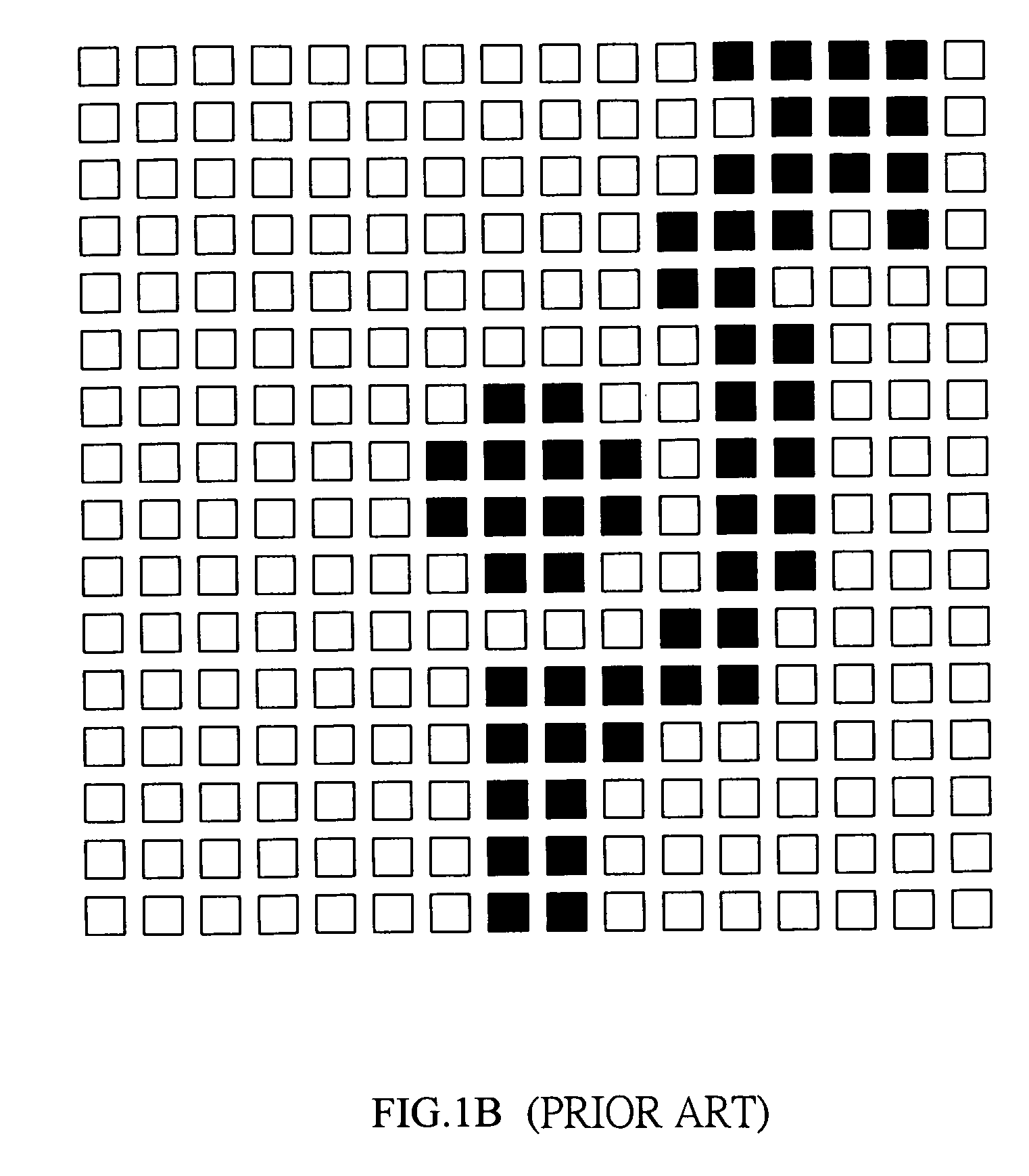
Besides, the dot matrix display means illustrated above also has the problem of having a serrate border at the edge of the image, such as the arc segment illustrated in FIG. 1A, furthermore, and the problem of not able to present more complex images due to the limited control points, as illustrated in FIG. 1B.
It is very difficult for user to identify the image of the front traffic circle which is displayed on dot matrix having insufficient resolution.

Method used


Image

  • Navigation image display apparatus and method thereof
  • Navigation image display apparatus and method thereof
  • Navigation image display apparatus and method thereof

Examples


Embodiment Construction

[0026]The present invention relates to a portable navigation device. While the specifications describe at least one embodiment of the invention considered best modes of practicing the invention, it should be understood that the invention can be implemented in many ways and is not limited to the particular examples described below or to the particular manner in which any features of such examples are implemented.

[0027]Please referring to FIG. 2A for a schematic view of the navigation image display apparatus with one embodiment in accordance with the present invention, the navigation image display apparatus 2 comprises a Vacuum Fluorescent Display (VFD) module 21 and a control module 22. The VFD module 21 comprises a display part 24 and at least one electric emitting part 23. The electric emitting part 23 is connected to a power source for generating a plurality of electrons 231, and the display part 24 has a plurality of display areas 241 which display image based on the electrons 23...


PUM


Abstract

This present invention provides a navigation image display apparatus and method thereof. The navigation image display apparatus comprises a Vacuum Fluorescent Display (VFD) module and a control module. The VFD module comprises at least one electric emitting part connected to a power source for generating a plurality of electrons; and a display part having a plurality of display areas which display images based on the electrons. The control module is operable to control the brightness of the display areas for displaying a navigation image. Preferably, the navigation image can comprise at least one image of turning left, straight ahead only, turning right, U turn left or U turn right, etc.

Description

FIELD OF THE INVENTION[0001]This invention relates to a navigation image display apparatus and method thereof, and more particularly to a navigation image display apparatus and method of using Vacuum Fluorescent Display (VFD) module to display the navigation image having multi-directional arrows.BACKGROUND OF THE INVENTION[0002]The navigation apparatus is getting popular at present, more and more drivers rely on the driving information provided from navigation apparatus, such as the map information, the destination route planning and the navigation information, etc. In order to prevent the driver from deviating his / her sight from the fore road while looking the navigation apparatus or further distracting to identify the navigation message so as to increases the risk factor of driving imperceptibly, many navigation apparatus are equipped with head-up display (HUD) to project the navigation message onto the windshield glass so that the driver can identify the navigation message withou...

Claims


Application Information

Patent Timeline
IPC IPC(8): G08G1/095
CPCG01C21/365G01C21/3632
Inventor YU, CHING HSIANG
Owner ELITEGROUP COMPUTER SYSTEMS
Why Eureka
Try Eureka