
Novel receiver architecture for pilot based OFDM systems

a receiver architecture and pilot technology, applied in the field of pilot-based ofdm receiver architecture, can solve the problems of high frequency offset, phase noise perturbation, clock offset, and high frequency offset of ofdm systems, and achieve the effects of robustness, cost-effectiveness, and hardware-efficien

Inactive Publication Date: 2009-03-19
EDGEWATER WIRELESS SYST
View PDF16 Cites 32 Cited by
  • Summary
  • Abstract
  • Description
  • Claims
  • Application Information

AI Technical Summary

Benefits of technology

"The present invention is about reducing phase errors in a pilot-based OFDM receiver by using known pilot sub-carriers to cancel out the effects of common phase offsets and sub-carrier dependent rotations. The invention is cost-effective, hardware-efficient, and robust. It can be easily applied to any pilot-based OFDM system and can be used in conjunction with synchronization circuitry. The invention also includes a method for determining sample timing errors and a solution for aligning local timing to the remote source."

Problems solved by technology

These bandwidth efficiencies provided by OFDM, however, do result in some difficulties and practical limitations.
In particular, OFDM systems are highly susceptible to frequency offset, phase noise perturbation, and clock offset.
These impairments generally result in an unwanted rotation of the received sub-carriers of the OFDM signal (e.g., a rotation of the received constellations of the individual sub-carriers).
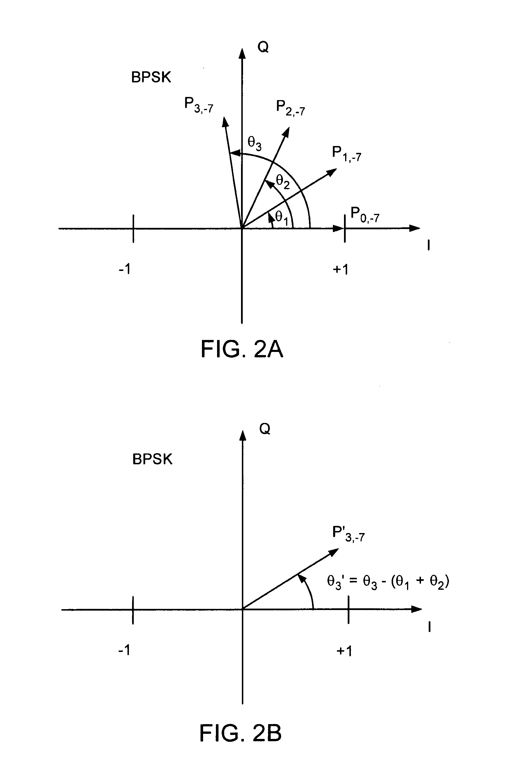
The unwanted rotations can be attributed to a common phase rotation and a sub-carrier dependent phase rotation, which can result in inter-carrier interference (ICI).
The effect of the sampling clock offset, even though subtler, since it accumulates slowly over time, can be detrimental over a large number of symbols.
This can cause substantial packet error rates for higher-order digital modulations including quadrature amplitude modulation (QAM), such as 16 QAM or 64 QAM.
One particular problem, however, associated with prior art solutions is their related cost and technical complexity.
This approach unnecessarily wastes channel bandwidth.
Unfortunately, the problems related to cost and complexity of the prior art solutions are amplified in WLAN applications.

Method used


Image

  • Novel receiver architecture for pilot based OFDM systems
  • Novel receiver architecture for pilot based OFDM systems
  • Novel receiver architecture for pilot based OFDM systems

Examples


example

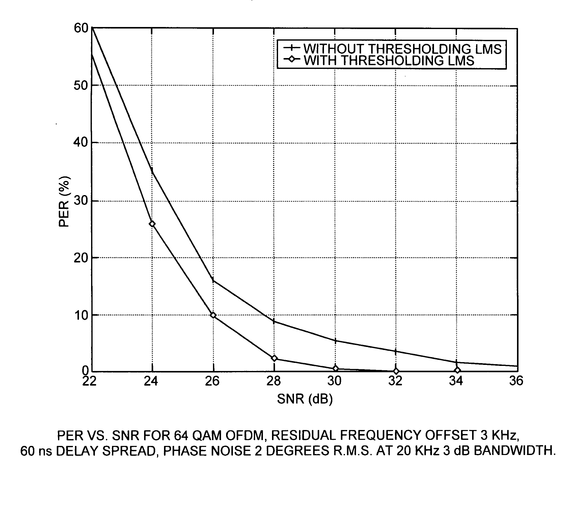
[0059]Simulation results for a 64 QAM, IEEE 802.11a OFDM system, showing the received constellation with and without LMS thresholding are shown in FIG. 8. The scenario uses a typical delay spread of 60 ns, a residual frequency offset of 3 KHz, and 2 degree, root-mean-square phase noise with a 3 dB bandwidth of 20 KHz. Perfect timing synchronization is assumed. There is nearly a 2 dB improvement resulting from the thresholding LMS scheme, over using no thresholding.

[0060]In some embodiments, the DSP 100 can be implemented in software. In other embodiments, the DSP can more preferably be implemented in hardware. In yet other embodiments, the DSP can be implemented using a combination of hardware and software.


PUM


Abstract

The invention relates to a novel methodology and apparatus for clock-offset compensation and common-phase offset correction in Frequency Division Multiplixing based wireless local area network (WLAN) environment, such as an Orthogonal Frequency Division Multiplexing (OFDM) environment. A curve fit, such as a threshold-based, least mean squares (LMS) fit of phase of the pilot sub-carriers in each OFDM symbol is used to estimate and counteract the rotation of the data sub-carriers due to residual frequency offset, low frequency phase noise, and clock offset. The invention is particularly well suited to wireless channels with multipath where pilots typically undergo frequency-selective fading. The thresholding LMS is implemented in a hardware-efficient manner, offering cost advantages over a weighted-LMS alternative. Additionally, the invention uses a unique phase-feedback architecture to eliminate the effects of phase wrapping, and avoid the need to refine channel estimates during packet reception.

Description

RELATED APPLICATION(S)[0001]This application is a continuation of U.S. application Ser. No. 10 / 713,562, filed Nov. 14, 2003, issued on Nov. 18, 2008 as U.S. Pat. No. 7,453,792, which claims the benefit of U.S. Provisional Application No. 60 / 426,215 filed Nov. 14, 2002. The entire teachings of the above applications are incorporated herein by reference.BACKGROUND OF THE INVENTION[0002]Orthogonal frequency division multiplexing (OFDM) is a robust technique for efficiently transmitting data over a channel. The technique uses a plurality of sub-carrier frequencies (sub-carriers) within a channel bandwidth to transmit the data. In particular, these sub-carriers are arranged for optimal bandwidth efficiency compared to more conventional transmission approaches, such as frequency division multiplexing (FDM). Namely, the more conventional approaches waste large portions of the channel bandwidth to separate and isolate the sub-carrier frequency spectra, thereby avoiding inter-carrier interfe...

Claims


Application Information

Patent Timeline
Patent Type & Authority Applications(United States)
IPC IPC(8): H04J11/00H04L27/26
CPCH04L27/266H04L27/2662H04L27/2675
Inventor CHADHA, KANUBHARDWAI, MANISH
Owner EDGEWATER WIRELESS SYST
Learn More