Method for producing rectangular flat secondary battery

a secondary battery and rectangular technology, applied in the direction of wound/folded electrode electrodes, cell components, sustainable manufacturing/processing, etc., can solve the problems of increasing internal resistance or variation, affecting the so as to prevent the occurrence of deflection of the electrode plate in compressing the electrode group and suppress the increase of internal resistance of the battery

Inactive Publication Date: 2009-03-26
PANASONIC CORP
View PDF3 Cites 39 Cited by
  • Summary
  • Abstract
  • Description
  • Claims
  • Application Information

AI Technical Summary

Benefits of technology

[0020]According to the present invention, with a center core member for applying a pressure to an electrode group inserted in a winding core hole of the electrode group, the electrode group is compressed and deformed into a flat shape. Thus, the occurrence of deflection of an electrode plate in compressing the electrode group can be prevented. Accordingly, a high capacity rectangular flat secondary battery in which increase in internal resistance of the battery is suppressed can be achieved.

Problems solved by technology

Specifically, it has been found that when a compound of Si, Sn or the like (for example, SiO, TiSi2 or the like) is used as an active material of a negative electrode, the problem becomes notable.
However, such an active material largely expands and shrinks.
Therefore, the increase in internal resistance or variation is caused as a result of increase in the degree of swelling of the electrode group, and thus the problem of swelling of deflection of an electrode plate again has become notable.

Method used


Image

  • Method for producing rectangular flat secondary battery
  • Method for producing rectangular flat secondary battery
  • Method for producing rectangular flat secondary battery

Examples


working example 1

(a) Forming of Positive Electrode Plate

[0050]A positive electrode mixture including lithium cobaltate as an active material, PVDF as a binder and acetylene black as a conducting agent was applied to an aluminum foil as a current collector and dried. The positive electrode mixture dried on the aluminum foil was rolled and then was cut so as to have a width of 29.5 mm. Thus, a hoop of a positive electrode plate was obtained.

(b) Forming of Negative Electrode Plate

[0051]A negative electrode mixture including artificial graphite as an active material, SBR as a binder and carboxymethyl cellulose as a thickener was applied to a copper foil as a collector and dried. The negative electrode mixture dried on the copper foil was rolled and then was cut so as to have a width of 30.6 mm. Thus, a hoop of a negative electrode plate was obtained.

(c) Adjustment of Electrolyte

[0052]1M of LiPF6 was dissolved in a nonaqueous mixed solvent containing ethylene carbonate, ethyl methyl carbonate and diethyl...

working example 2

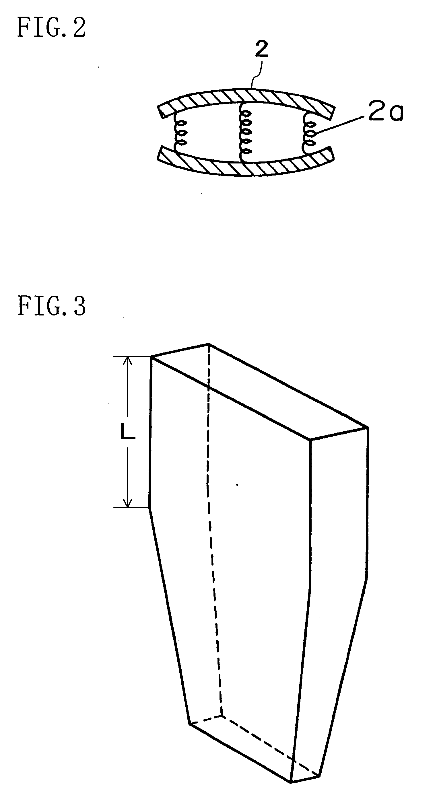
[0057]In contrast to Working Example 1, as a material of the center core member 2, polypropylene (with a Young's modulus of 4.5 GPa) was used. Other than that, a lithium ion secondary battery was produced in the same manner as in Working Example 1.

working example 3

[0058]In contrast to Working Example 1, as a material of the center core member 2, PVDF (with a Young's modulus of 2.0×10⁻³ GPa) was used. Furthermore, the center core member 2 was formed so as to have the same dimensions as those in Working Example 1 but have a plate-shape. Other than that, a lithium ion secondary battery was produced in the same manner as in Working Example 1.


PUM

PropertyMeasurementUnit
Young's modulusaaaaaaaaaa
widthaaaaaaaaaa

Abstract

A positive electrode plate and a negative electrode plate are spirally wound with a separator interposed therebetween to form an electrode group 3 having a circular shape or an oval shape. Next, a center core member 2 for applying a pressure to the electrode group 3 is inserted in a winding core hole 6 of the electrode group 3. Thereafter, the electrode group 3 is deformed into a flat shape. Then, the flat electrode group 3 is accommodated in a rectangular flat armoring can 4 with a base and an opening portion of the armoring can 4 is sealed, thereby producing a rectangular flat secondary battery.

Description

TECHNICAL FIELD[0001]The present invention relates to a method for producing a rectangular flat secondary battery with excellent stability in battery properties and high capacity.BACKGROUND ART[0002]In recent years, more and more portable or cordless household electronic appliances have been used. With reduction in size and weight of electronic appliances, nonaqueous electrolyte secondary batteries such as nickel cadmium battery, nickel-metal hydride battery, small sealed lead acid storage battery and the like have come into use as a power supply for driving electric appliances. In a nonaqueous electrolyte secondary battery, in order to achieve highly efficient charge and discharge performance, a positive electrode plate and a negative electrode plate are spirally wound with a separator interposed therebetween to form an electrode group in general.[0003]As the size and weight of electronic appliances have been reduced, in view of effectively utilizing a space of an electronic applia...

Claims


Application Information

Patent Timeline
Patent Type & Authority Applications(United States)
IPC IPC(8): H01M6/00H01M10/0566H01M10/0587H01M50/147
CPCH01M2/0217H01M2/0404H01M4/602H01M4/661Y10T29/4911H01M10/0431H01M10/0436H01M10/0468H01M10/0413Y02E60/10H01M50/103H01M50/147Y02P70/50H01M10/0587H01M4/38H01M10/38
Inventor HIRAKAWA, YASUSHISHIRANE, TAKAYUKI
Owner PANASONIC CORP
Why Eureka
Try Eureka