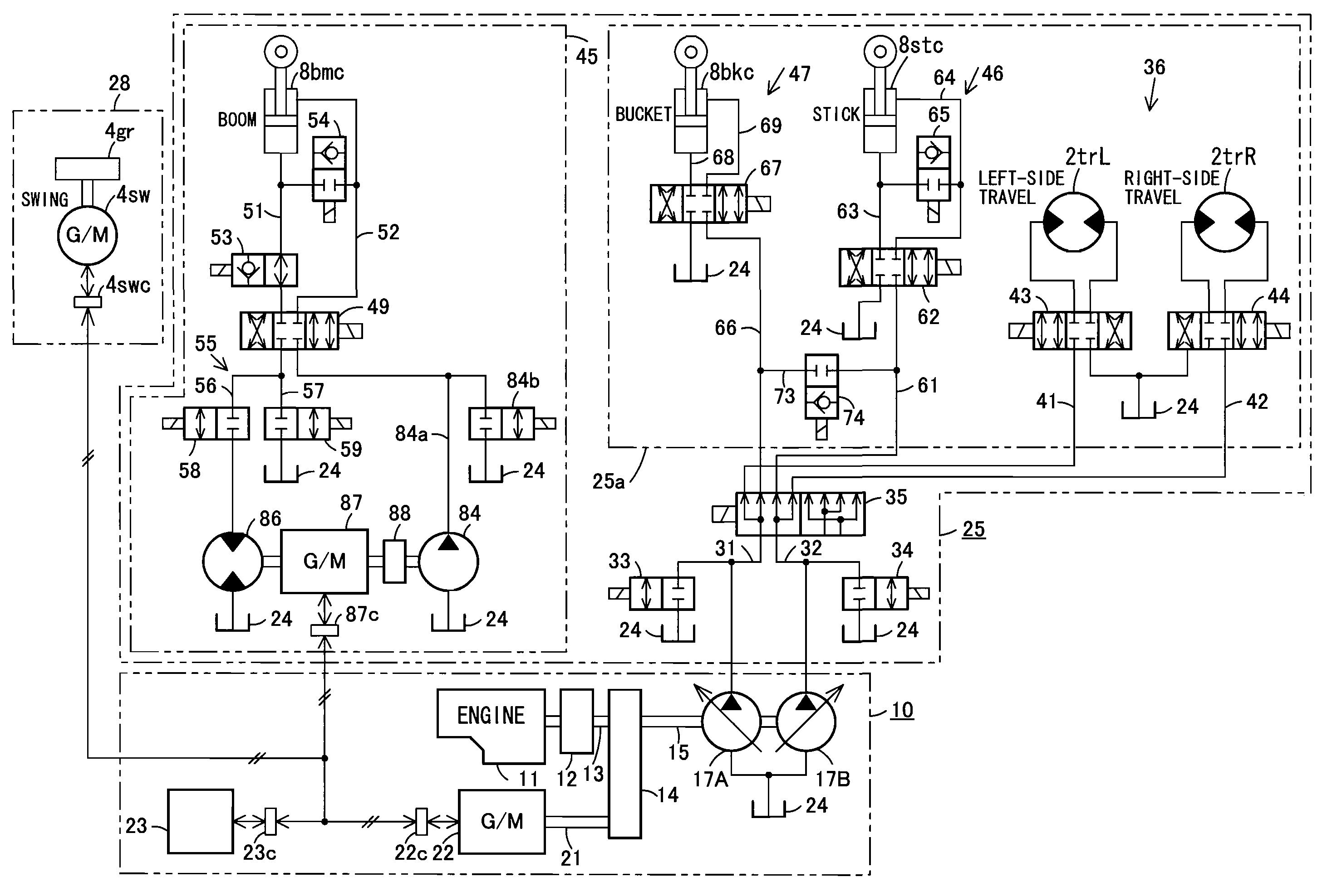
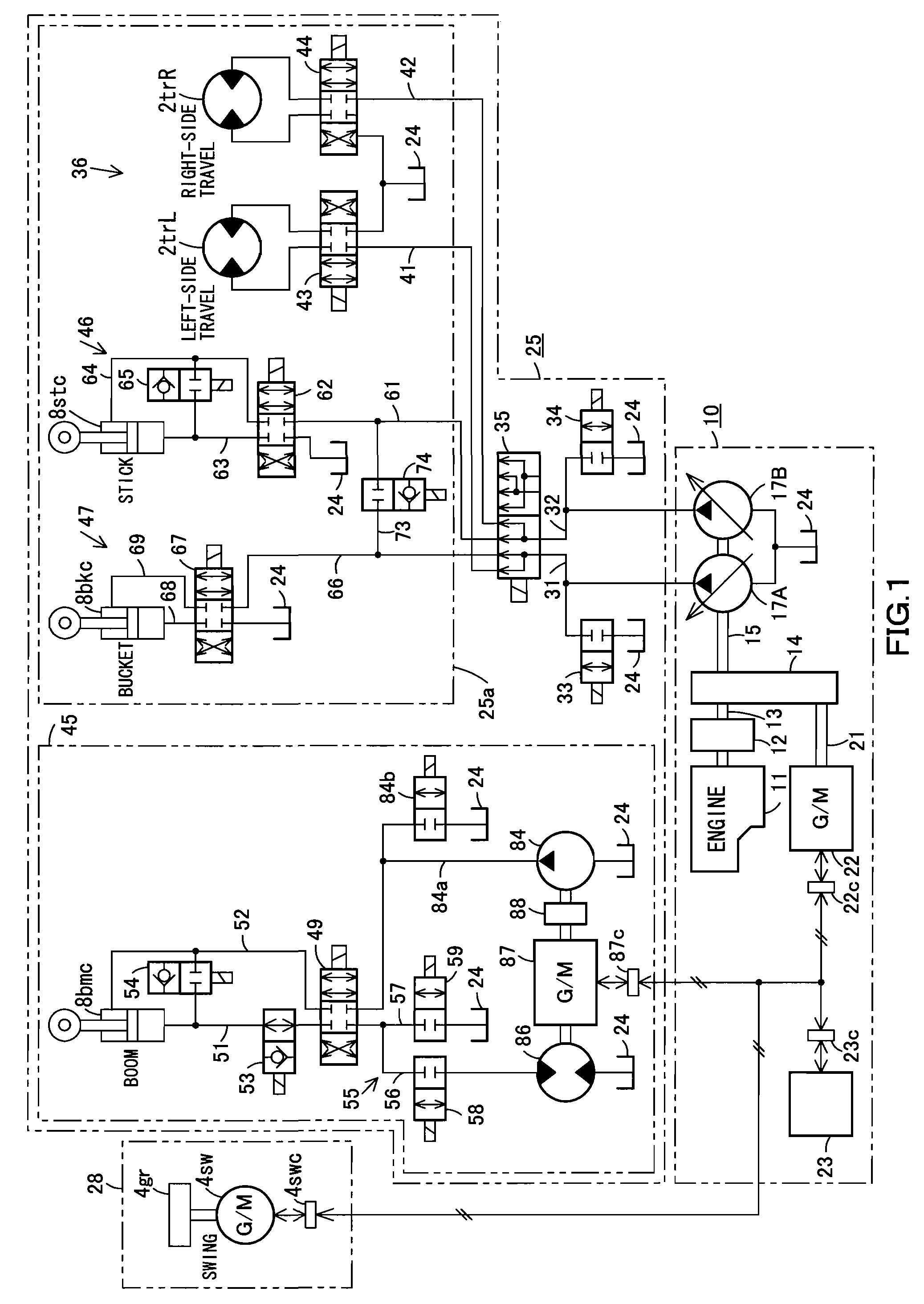
[0016]According to the present invention, the boom control circuit, which includes the boom pump provided separately from the main pump of the
hybrid type drive
system and serves to control
hydraulic fluid fed from the boom pump to the boom cylinder, is adapted to function independently of the travel / stick / bucket control circuit, which serves to control hydraulic fluid fed from the main pump of the
hybrid type drive system to the travel motor, the stick cylinder, and the bucket cylinder. Therefore, the flow rate required by the boom cylinder can be easily ensured by, for example, controlling the rotation speed of the boom pump by means of the boom motor generator without being affected by the hydraulic fluid fed to the travel motor, the stick cylinder, or the bucket cylinder. Furthermore, the boom control circuit is capable of disengaging the
clutch so that the
energy recovery motor driven by return fluid discharged from the boom cylinder efficiently inputs driving power to the boom motor generator, which is under no-load condition, and that the generated
electric power is stored in the electric
power storage device. The boom control circuit is also capable of engaging the
clutch so that electric power fed from the electric
power storage device enables the boom motor generator to function as an
electric motor to drive the boom pump, thereby feeding hydraulic fluid from the boom pump to the boom cylinder. Thus, energy of return fluid discharged from the boom cylinder can be effectively recovered even in an open circuit.
[0017]According to another embodiment of the present invention, when controlling hydraulic fluid fed from the main pump of the
hybrid type drive system to the travel motor, the boom cylinder, the stick cylinder, and the bucket cylinder, the hydraulic
actuator control circuit enables the energy
recovery motor driven by return fluid discharged from the boom cylinder to input driving power to the boom motor generator so that the generated electric power is stored in the electric
power storage device of the
hybrid type drive system. The hydraulic
actuator control circuit also enables the boom motor generator to be driven by electric power fed from the electric power storage device of the hybrid type drive system so that the boom motor generator functions as an
electric motor to drive the boom assist pump, thereby feeding hydraulic fluid from the boom assist pump to the boom cylinder. Thus, energy of return fluid discharged from the boom cylinder can be effectively recovered even in an open circuit.
[0019]According to an embodiment of the present invention, the energy
recovery motor is provided in one of the return passages through which return fluid discharged from the boom cylinder flows, and the flow
rate ratio control valve controls a flow
rate ratio of a flow rate of the return fluid passing through the energy
recovery motor and a flow rate of the return fluid in the other return passage, which branches off the first mentioned return passage at a location upstream of the energy recovery motor. Therefore, the configuration according to the present invention is capable of gradually increasing the flow rate proportion of the fluid distributed towards the energy recovery motor from the moment when return fluid starts to flow from the boom cylinder, thereby preventing occurrence of shock, as well as ensuring
stable function of the boom cylinder by preventing a sudden change in load to the boom cylinder.
[0020]According to the present invention disengaging the clutch enables the energy recovery motor, which is driven by return fluid discharged from the boom cylinder, to efficiently input driving power to the boom motor generator, which is under no-load condition, so that the generated electric power is stored in the electric power storage device of the hybrid type drive system. When the clutch is engaged, electric power fed from the electric power storage device of the hybrid type drive system enables the boom motor generator to function as an electric motor to drive the boom assist pump, thereby feeding hydraulic fluid from the boom assist pump to the boom cylinder.
[0021]According to another embodiment of the present invention, the
solenoid valve between bucket and boom is disposed in the boom cylinder hydraulic fluid feeding passage. Therefore, by opening this
solenoid valve, a combined amount of hydraulic fluid can be fed from one of the main pumps and the boom assist pump to the boom cylinder. Therefore, it is possible to increase the speed of boom raising action by the boom cylinder and improve working efficiency. Furthermore, a
high pressure to the bucket cylinder can be ensured by closing the
solenoid valve. As the solenoid valve between bucket and stick is disposed in the circuit-to-circuit communicating passage between bucket and stick, opening this solenoid valve ensures supply of hydraulic fluid from another main pump to the stick cylinder, thereby increasing the speed of action of the stick cylinder and improving working efficiency. Furthermore, a
high pressure to the bucket cylinder can be ensured by closing the solenoid valve.
[0022]According to the present invention, the solenoid valve between stick and boom is disposed in the circuit-to-circuit communicating passage between stick and boom for providing fluid communication between the stick cylinder hydraulic fluid feeding passage and the head-side of the boom cylinder. Therefore, by opening this solenoid valve, hydraulic fluid can be fed to the head-side of the boom cylinder not only from the first-mentioned main pump and the boom assist pump but also from the second-mentioned main pump, thereby increasing the speed of boom raising action by the boom cylinder and improving working efficiency. Furthermore, supply of hydraulic fluid to the stick cylinder can be ensured by closing the solenoid valve.

