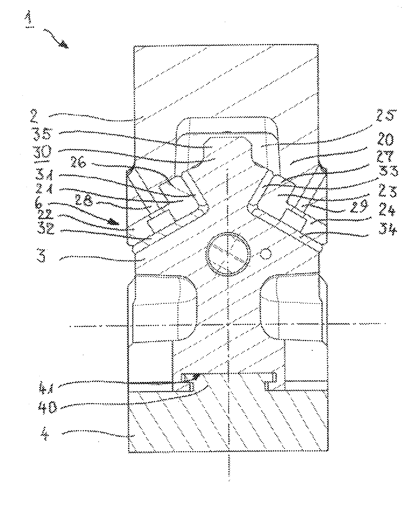
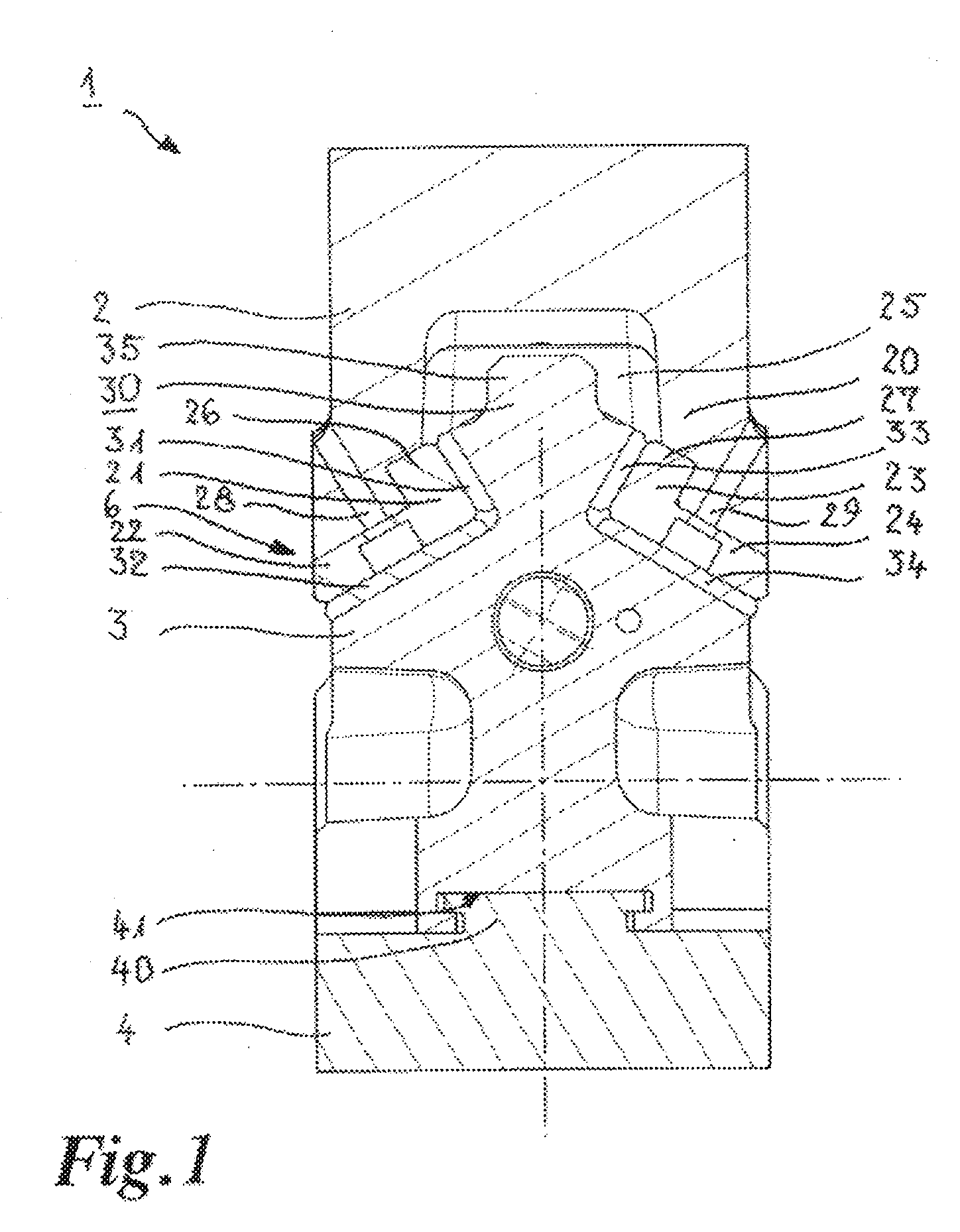
[0016]That therefore provides a wedge drive or cotter key in which the movable slider element has a dovetail-like or prismatic side, wherein the slider element receiving means is in the form of a corresponding counterpart portion so that the slider, element with its dovetail-like or prismatic side can engage into the slider element receiving means and can be guided and held therein. The surfaces on the slider element and / or the slider element receiving means, that are respectively provided by the dovetail shape and the
prism shape, bear against each other, in which case forces directed in different directions can be carried without any problem by virtue of the surfaces which are at an angle relative to each other, in the dovetail or
prism shape. The dovetail shape means that, after being inserted into the correspondingly shaped receiving configuration of the slider element receiving means, the movable slider element is safeguarded against falling out or
lateral displacement, without further measures.
[0031]In the case of a suspended upper part slider or wedge drive the weight of the slider element acts on the surfaces of the slider element receiving means, which bear in positively locking relationship against the slider element sliding surfaces of the dovetail guide arrangement, and exerts a downwardly directed spreading force on those surfaces of the sliding element receiving means. By virtue of the positively locking
shoulder support for the slider element with respect to the slider element receiving means however those
lateral thrust forces are compensated so that permanent and stable fixing of the slider element to the slider element receiving means and the sliding plates on the slider element and the slider element receiving means is possible. Therefore the fixing screws of the sliding plates are not subject to any forces such as to damage them, in particular tensile forces. As guidance for the slider element along the slider element receiving means by virtue of the dovetail guide arrangement is possible with a high
degree of precision and without being sensitive to
lateral thrust forces as well as being inexpensive to manufacture, without the provision of further components in the form of a linear guide means, the result is a compact wedge drive with a
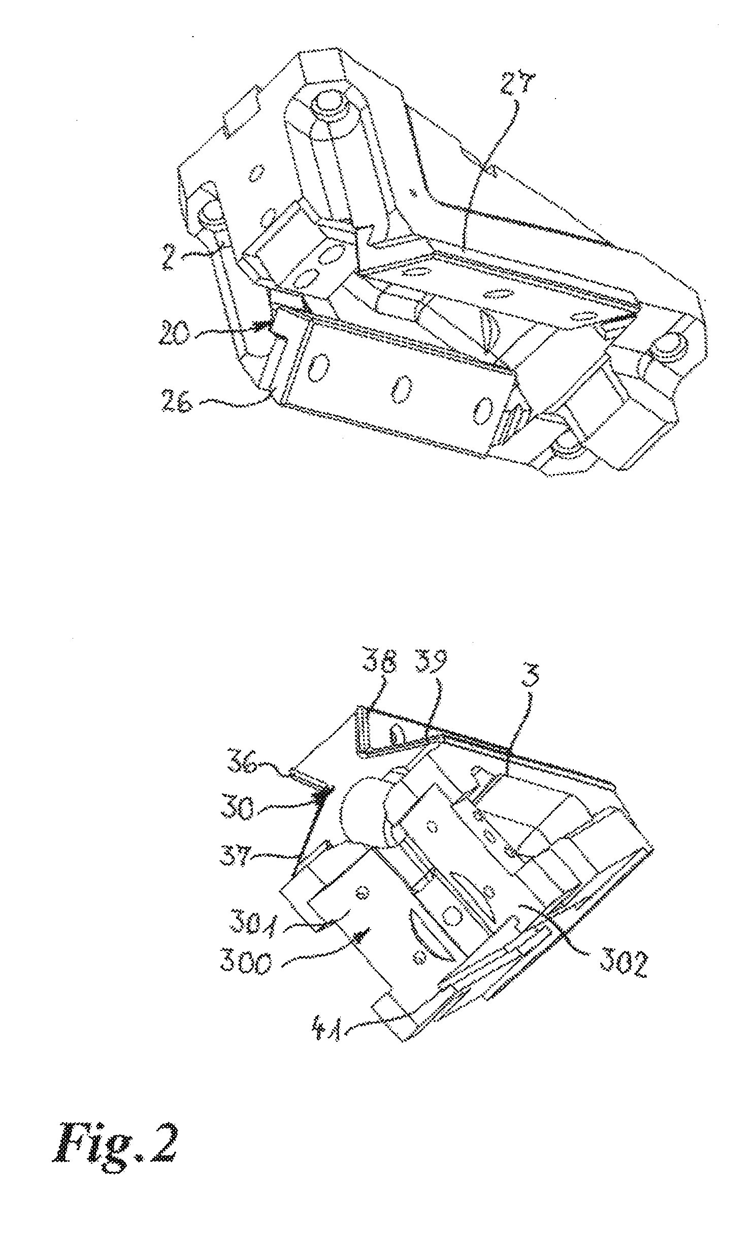
very high level of accuracy of motion, which is also insensitive in relation to manufacturing tolerances. As clamp guides or further elements are no longer required, not only can the costs be reduced in comparison with the solutions in the state of the art, but the process reliability is also increased and a possible risk of accident reduced. As the slider element only needs to be pushed into the slider element receiving means,
assembly of the wedge drive is simplified in comparison with the solutions in the state of the art. It is possible to dispense with a cost-intensive operation of
grinding in the guide elements as the prism guides or dovetail guide of the slider element receiving means, the slider element and the driver element are insensitive in relation to tolerances in manufacture. The self-centering effect achieved by the prism guides also leads to a
very high level of accuracy in terms of motion in regard to carrying lateral thrust forces. By virtue of the compact structure of the wedge drive it is not only suitable for a small structural space available within a pressing tool, but, as will be appreciated, it is also suitable for uses involving larger dimensions. The prism guide means or the dovetail-like guide means provided between the slider element and the slider element receiving means can thus be used to equip small, medium and large-format wedge drives, thus affording a
large range of uses.BRIEF DESCRIPTION OF THE DRAWINGS

