Composite valve assembly for aircraft environmental control systems

a technology for aircraft environmental control systems and valve assemblies, applied in valve housings, valve member-seat contacts, mechanical equipment, etc., can solve the problems of insufficient use of lightweight materials in structural applications, such as valve flow bodies, and achieve high-performance engineering and high-performance effects

Inactive Publication Date: 2009-03-26
HONEYWELL INT INC
View PDF27 Cites 8 Cited by
  • Summary
  • Abstract
  • Description
  • Claims
  • Application Information

AI Technical Summary

Benefits of technology

[0007]There has now been developed a composite valve assembly comprised of an injection molded flow body having at least one inlet port, at least one outlet port. A flow passage is formed there between. The injection molded flow body is formed of a high performance engineering thermoplastic resin. The valve assembly further includes an electrical bonding connection coupled to the injection molded flow body to a bonding path between the injection molded flow body and an external ground point.
[0008]In a further embodiment, still by way of example only, there is provided a composite valve assembly for an environmental control system (ECS) comprised of an injection molded flow body having at least one inlet port, at least one outlet port, and a flow passage there between. The injection molded flow body is formed of a high performance engineering thermoplastic resin selected from a group consisting of: polyetheretherketone (PEEK), polyphenylenesulfide (PPS), polyetherimide (PEI), and polyethersulfone (PES). The valve assembly further includes an electrical bonding connection coupled to the injection molded flow body and providing a bonding path between the injection molded flow body and an external ground point.
[0009]In still a further embodiment, and still by way of example only, there is provided a composite valve assembly for environmental control systems (ECS) of an aircraft comprised of an injection molded flow body having at least one inlet port, at least one outlet port, and a flow passage there between. The injection molded flow body is formed of a high performance engineering thermoplastic resin selected from a group consisting of: polyetheretherketones (PEEK), polyphenylenesulfide (PPS), polyetherimide (PEI), and polyethersulfone (PES) and a plurality of fiber reinforcements homogenously suspended therein the high performance engineering thermoplastic resin. The valve assembly further includes an electrical bonding connection coupled to the injection molded flow body and providing a bonding path between the injection molded flow body and an external ground point.
[0010]Other independent features and advantages of the improved composite valve assembly will become apparent from the following detailed description, taken in conjunction with the accompanying drawings which illustrate, by way of example, the principles of the invention.

Problems solved by technology

In the environmental control system (ECS) pack bay of commercial aircraft, which is an unpressurized and non-temperature controlled environment, the use of lightweight materials in structural applications, such as valve flow bodies, has not been achieved.
These types of valve flow bodies are viewed as structurally critical components because the postulated failure of such poses a risk of aircraft cabin depressurization and can be a cause of non-compliance with a minimum equipment list.

Method used


Image

  • Composite valve assembly for aircraft environmental control systems
  • Composite valve assembly for aircraft environmental control systems
  • Composite valve assembly for aircraft environmental control systems

Examples


Embodiment Construction

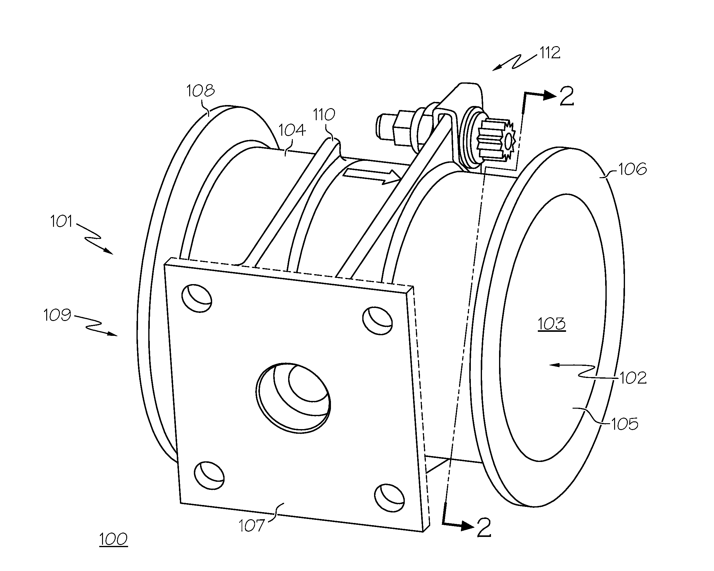
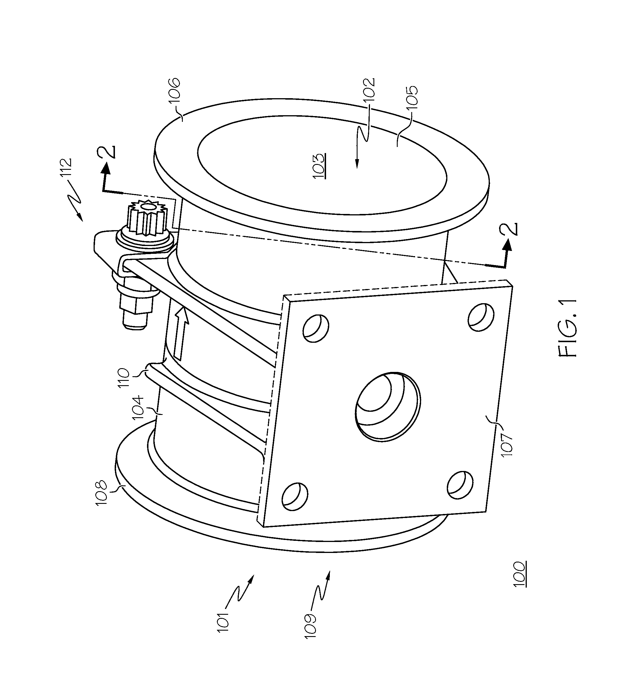
[0014]The following detailed description of the invention is merely exemplary in nature and is not intended to limit the invention or the application and uses of the invention. Furthermore, there is no intention to be bound by any theory presented in the preceding background or the following detailed description. It should be understood that although the valve assembly is described in conjunction with a turbofan jet engine, it may also be used in any application where a valve assembly is utilized. It should additionally be understood that use of the term “pneumatic” may be interpreted as describing the fluid medium flowing through a pressure vessel, but may also be used to describe the means of actuation of a valve. It should additionally be understood that anticipated by this disclosure is the inclusion of electric, hydraulic, and manual valve actuation.

[0015]FIG. 1 is a simplified isometric view of a portion of a valve assembly 100. The valve assembly 100 is configured to control ...


PUM


Abstract

A valve assembly is provided including an injection molded flow body having at least one inlet port, at least one outlet port, and a flow passage there between. The injection molded flow body is formed of a high performance engineering thermoplastic resin. A plurality of reinforcement fibers may be homogeneously suspended in the high performance engineering thermoplastic resin and provide increased strength and temperature capability for use in high temperature applications.

Description

FIELD OF THE INVENTION[0001]The present invention generally relates to a valve assembly and, more particularly, to a composite valve flow body for use in conjunction with aircraft environmental control systems.BACKGROUND OF THE INVENTION[0002]Many relatively large turbine engines use pneumatic valves to control fluid flow. Some specific examples of pneumatic valves utilized in turbine engines include high stage bleed air valves, mid-stage bleed air valves, bleed air isolation valves, pressure regulating and shutoff valves, load control valves, anti-ice valves, trim air valves, and temperature control valves.[0003]In one specific example, pressure regulating, temperature modulating, and flow control valves may be coupled to a high pressure fluid source such as compressed air taken directly from a turbofan jet engine or an electrically driven turbocompressor for use in environmental control systems (ECS) of aircraft, including heating, ventilating, and air conditioning (HVAC) systems....

Claims


Application Information

Patent Timeline
Patent Type & Authority Applications(United States)
IPC IPC(8): F16K27/00
CPCF16L9/128
Inventor EKSTROM, ERIC J.ARMSTRONG, GARY E.VELASQUEZ, RAULVASQUEZ, JOHN A.MORK, JASON D.
Owner HONEYWELL INT INC
Why Eureka
Try Eureka