High Sensitivity GPS Receiver

a gps receiver, high-sensitivity technology, applied in the field of satellite navigation receivers, can solve the problems of low-cost gps receivers that typically receive, many impediments, and satellite signals that always have some doppler-induced distortion

Inactive Publication Date: 2009-03-26
QUALCOMM INC
View PDF13 Cites 20 Cited by
  • Summary
  • Abstract
  • Description
  • Claims
  • Application Information

AI Technical Summary

Benefits of technology

[0010]A high-sensitivity GPS receiver can include an antenna, an analog section for receiving an output of the antenna, a digital section for receiving an output of the analog section, and a processor for receiving an output of the digital section. Notably, the digital section can include a plurality of acquisition channels, wherein at least one acquisition channel can include a configurable correlator. This configurable correlator can include a pre-summer, a delay line, a plurality of correlation multipliers, an adder tree, an adder, and a correlation memory. The pre-summer can receive resampled digital baseband data, remove Doppler effects, and add two data samples of Doppler-corrected, digital baseband data. In one embodiment, the pre-summer can include a mixer coupled to the resampled digital baseband data and an estimated Doppler frequency, a register coupled to an output of the mixer, and a first adder coupled to an output of the mixer and an output of the register.

Problems solved by technology

However, low cost GPS receivers typically receive only on the one of these bands.
There are many impediments to receiving signals from GPS satellites.
Thus, the signals from the satellites will always have some Doppler induced distortion.
In addition, the L1 band is substantially a line-of-sight frequency band, i.e. the signals transmitted at those frequencies generally travel by line-of-sight, and may be easily blocked by buildings or terrain, and more prone to multipath distortion.
Other interference sources that may impede signal reception are thermal noise, atmospheric propagation interference, and so forth.
Therefore, GPS satellite signal reception may be further hindered when the GPS receiver is inside of a building because the roof and walls of the structure may reduce the amount of satellite signal received.
However, still other product opportunities may present themselves as GPS receivers become even smaller.
Furthermore, many consumer product opportunities are typically cost-sensitive.

Method used


Image

  • High Sensitivity GPS Receiver
  • High Sensitivity GPS Receiver
  • High Sensitivity GPS Receiver

Examples


Embodiment Construction

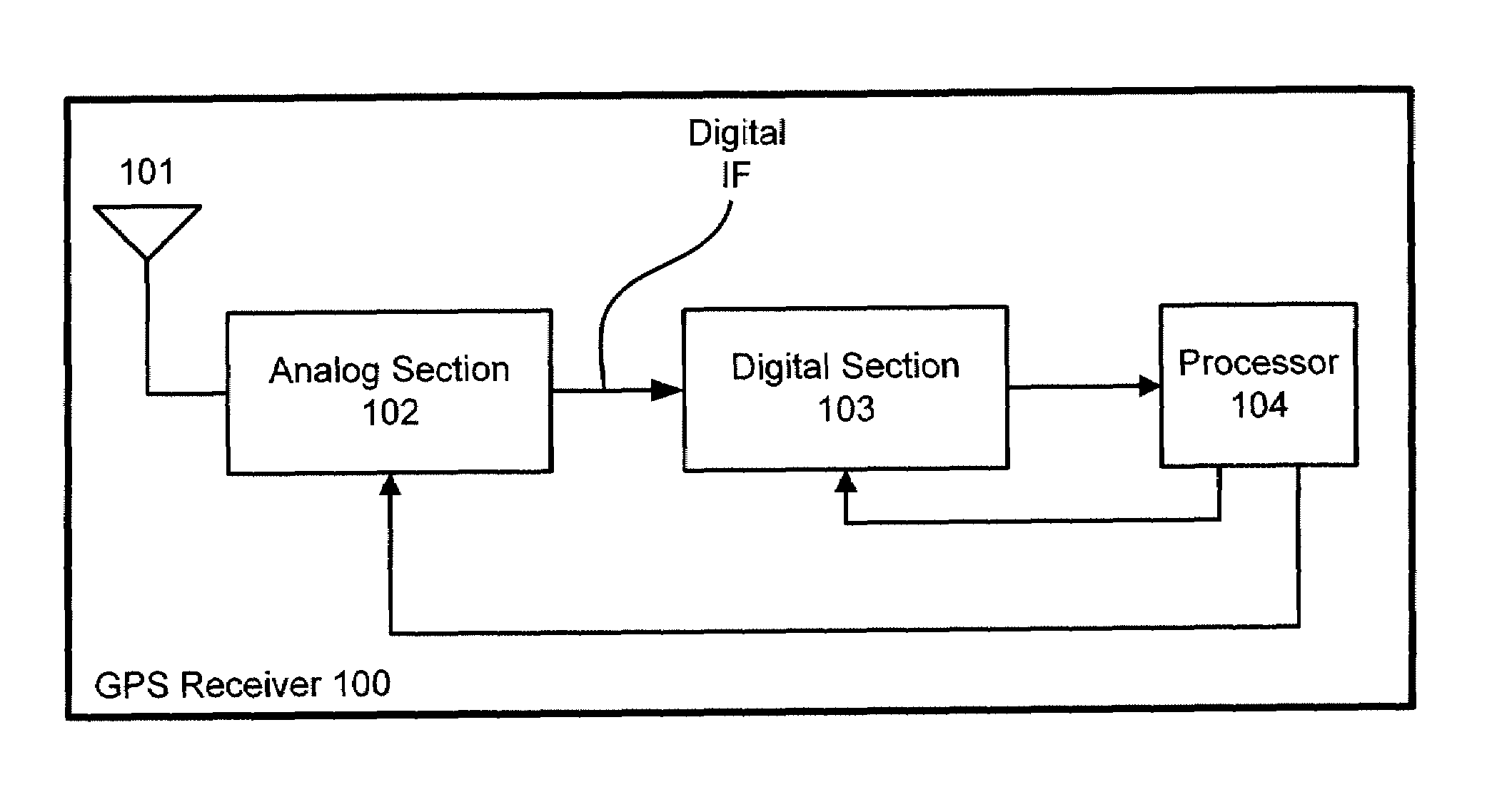
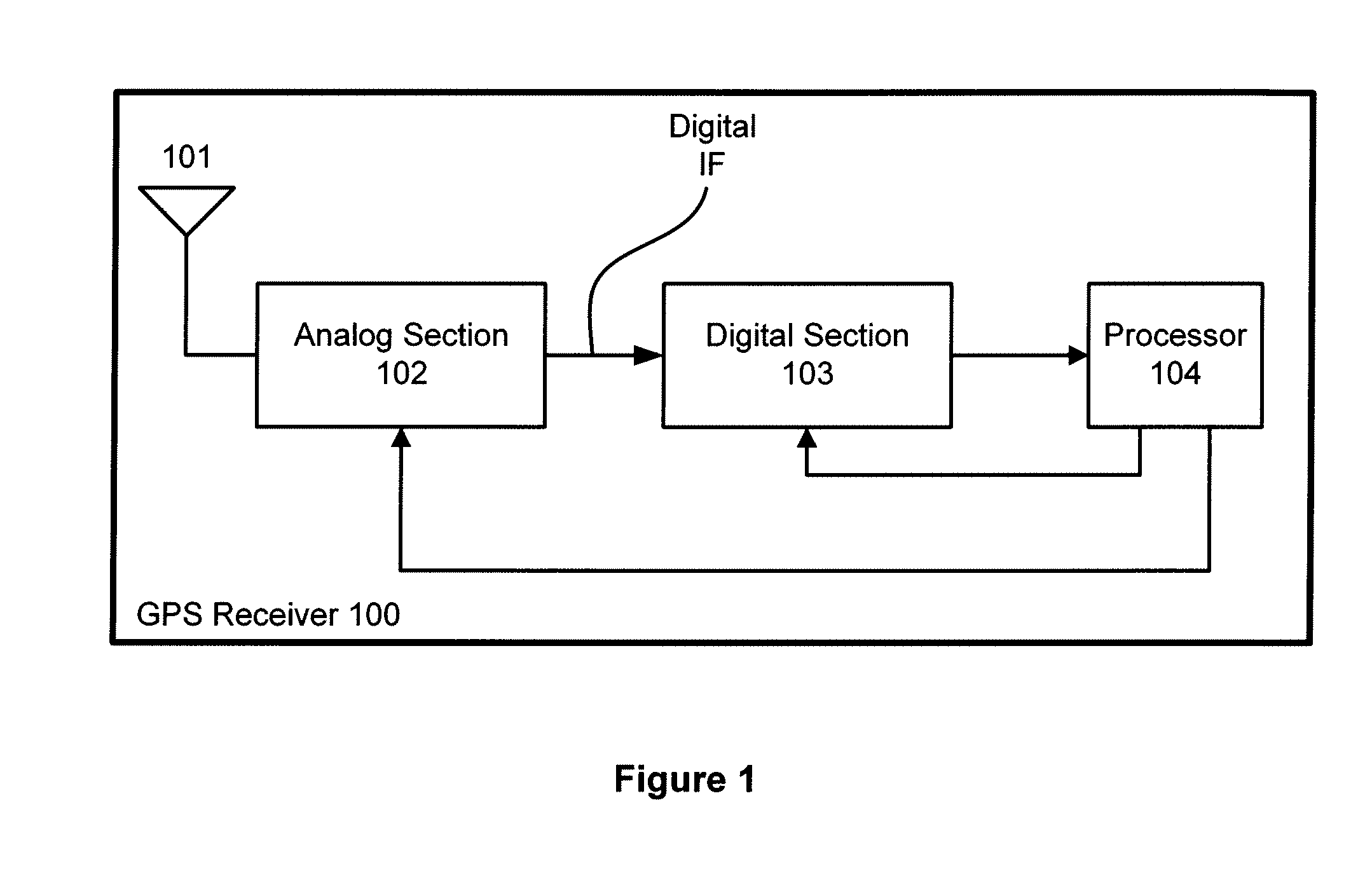
[0035]FIG. 1 is a conceptual diagram of a GPS receiver 100. GPS receiver 100 includes, without limitation, an antenna 101, an analog section 102, a digital section 103, and a processor 104. GPS satellite signals are received by antenna 101 and are coupled to an input of analog section 102. Analog section 102 processes the GPS satellite signals and produces a digital intermediate frequency (IF) signal by sampling the GPS satellite signal with an analog to digital converter (ADC). In one embodiment, the sample rate may be approximately 16 mega-samples per second (Ms / s). The digital IF signal is coupled to the input of digital section 103. Digital section 103 uses the digital IF signal to acquire and track satellites from within the GPS satellite constellation by producing acquisition and tracking data that is coupled to processor 104. Processor 104 may be a central processing unit CPU, a microprocessor, a digital signal processor, or any other such device that may read and execute pro...


PUM


Abstract

A high sensitivity GPS receiver includes an acquisition engine and a tracking engine. The acquisition engine processes GPS satellite data at data rate that is substantially equal to twice the coarse acquisition (CA) code chip rate. This data rate advantageously enables the acquisition engine to process GPS satellite data with relatively less hardware area than traditional GPS acquisition approaches. In one embodiment, the high efficiency acquisition engine may be over-clocked, thereby allowing different phases of a CA code to be correlated quickly. The tracking engine can advantageously processes GPS satellite data at a data rate that does not have an integer relationship to the CA code chip rate.

Description

RELATED APPLICATIONS[0001]This application claims priority of U.S. Provisional Patent Application 60 / 946,675, entitled “High Sensitivity GPS Receiver” filed Jun. 27, 2007.BACKGROUND OF THE INVENTION[0002]1. Field of the Invention[0003]Embodiments of the present invention generally relate to satellite navigation receivers and more particularly to high sensitivity GPS receivers.[0004]2. Description of the Related Art[0005]Global positioning system (GPS) receivers typically use data from three or more orbiting satellites to determine navigational information such as position and velocity. There may be up to thirty functional satellites included in the GPS constellation, however, only a portion of those satellites may be visible to a particular GPS receiver at a given time. GPS satellites typically transmit information on two bands: the L1 band with a carrier frequency of approximately 1575.42 MHz and the L2 band with a carrier frequency of approximately 1227.40 MHz. Traditionally, only...

Claims


Application Information

Patent Timeline
Patent Type & Authority Applications(United States)
IPC IPC(8): G01S1/00
CPCG01S19/24G01S19/30H04L7/0016G01S19/37G01S19/36
Inventor SUN, QINFANGYEH, WEN-CHANGCHEN, HO-CHUNG
Owner QUALCOMM INC
Why Eureka
Try Eureka