Control Method of Exhaust Gas Purification System and Exhaust Gas Purification System

a technology of exhaust gas purification system and control method, which is applied in the direction of machine/engine, vehicle components, process and machine control, etc., can solve the problems of difficult re-generation of filters, low difficulty in controlling the temperature of exhaust gas, so as to achieve precise control and avoid oil dilution

Active Publication Date: 2009-03-26
ISUZU MOTORS LTD
View PDF8 Cites 35 Cited by
  • Summary
  • Abstract
  • Description
  • Claims
  • Application Information

AI Technical Summary

Benefits of technology

[0029]According to the control method of the exhaust gas purification system and the exhaust gas purification system of the present invention, an exhaust gas purification device is provided for purifying components in the exhaust gas of an internal combustion engine such as a diesel engine. When conducting a regenerative control for recovering purification ability of this exhaust gas purification device, the regenerative control including post injections as part of an in-cylinder fuel injection control, the post injection quantities themselves, and not post injection times, are accumulated. For this reason, a more precise control can be executed, and oil dilution can be avoided before it occurs.

Problems solved by technology

However, in the case of low exhaust temperature (for example, in cases of an ongoing low exhaust temperature state, such as when the internal combustion engine is operating at idling or driving at low load / low speed), the exhaust gas temperature is low, the catalyst temperature decreases, and the catalyst is not activated.
For this reason, oxidation reactions are not promoted, and it becomes difficult to regenerate the filter by oxidizing PM.
Consequently, PM accumulation to the filter continues, and since filter clogging progresses, there arises the problem of exhaust pressure increase due to the clogging of this filter.
However, the post injection execution time and the fuel injection quantity diluting the lubricating oil are not necessarily proportional, and this fuel injection quantity changes according to factors such as changes in injection pressure.
For this reason, if a control is conducted based on injection time, the fuel injection quantity becomes too large, and the quantity of oil dilution increases.
However, in this type of control, since a very fine control is conducted for each cylinder, it takes time to calculate the configured values.
For this reason, although control is possible in an exhaust purification device always conducting post injections and the like, there is a problem in that control over brief intervals in a regenerative control is not practical.
In addition, there is also a problem in that the program for conducting this kind of control is complicated, and the creation thereof requires a great deal of time and effort.

Method used


Image

  • Control Method of Exhaust Gas Purification System and Exhaust Gas Purification System
  • Control Method of Exhaust Gas Purification System and Exhaust Gas Purification System
  • Control Method of Exhaust Gas Purification System and Exhaust Gas Purification System

Examples


Embodiment Construction

[0037]Hereinafter, an embodiment of the control method of the exhaust gas purification system and the exhaust gas purification system in accordance with the present invention will be described by taking as an example an exhaust gas purification system provided with a continuous regeneration type DPF device configured with a combination of an oxidation catalyst and a catalytic filter (a filter carrying catalyst), and with reference to accompanying drawings.

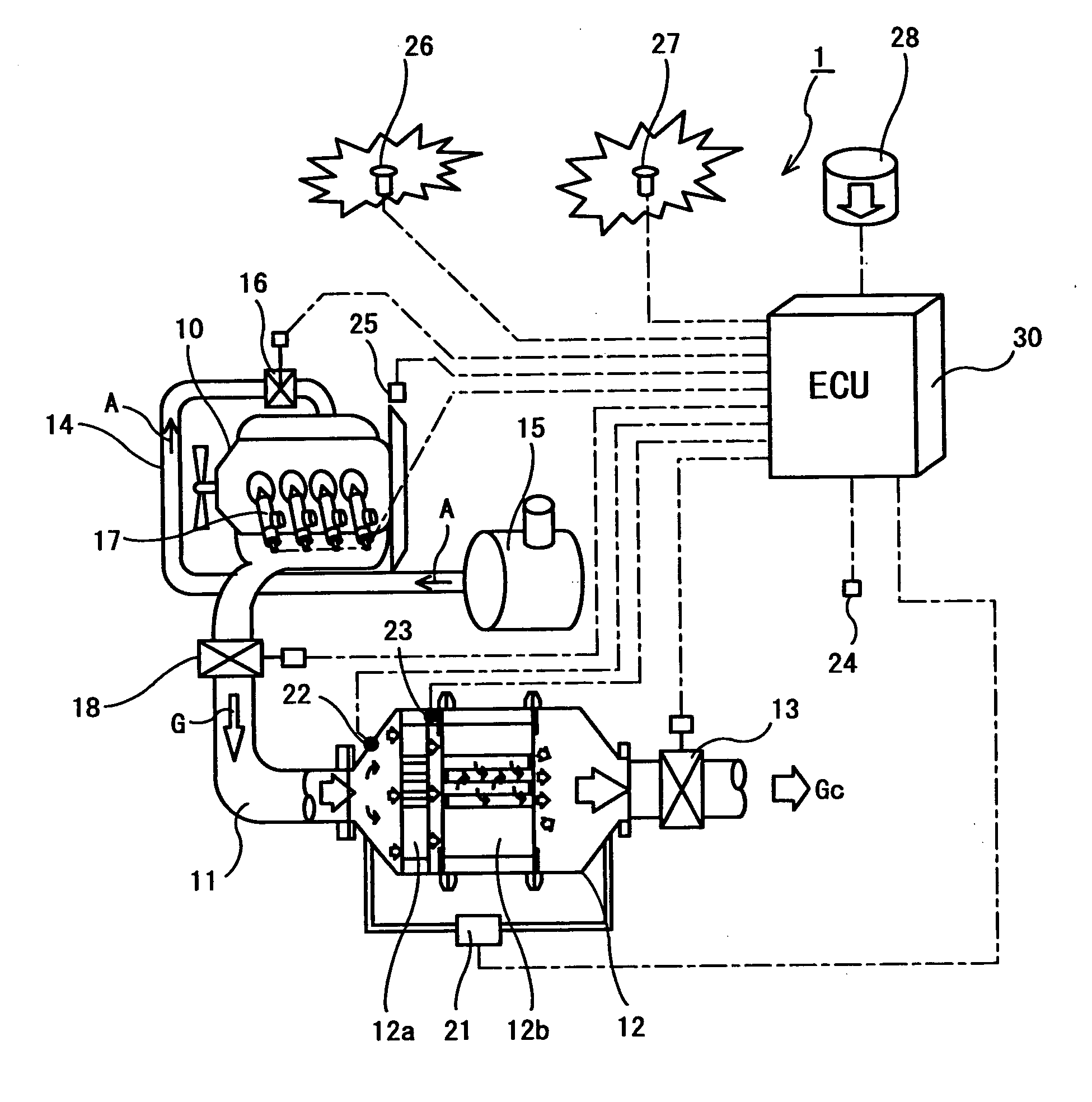
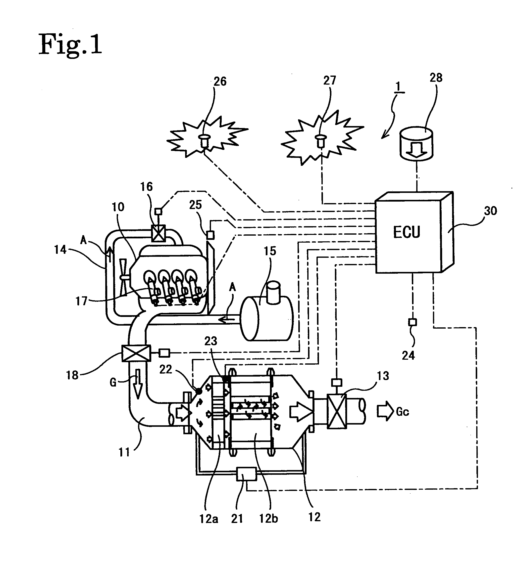
[0038]FIG. 1 shows the configuration of an exhaust gas purification system 1 of the present embodiment. This exhaust gas purification system 1 is configured having a continuous regeneration type DPF device 12 in an exhaust passage 11 of a diesel engine (internal combustion engine) 10. This continuous regeneration type DPF device 12 is configured having an upstream oxidation catalyst 12a, and a downstream catalytic filter 12b. In addition, an exhaust throttle valve (exhaust throttle) 13 is provided downstream of the continuous regen...


PUM

PropertyMeasurementUnit
exhaust gas temperatureaaaaaaaaaa
speedaaaaaaaaaa
atmospheric pressureaaaaaaaaaa

Abstract

An exhaust gas purification system has an exhaust gas purification device (12) for purifying components in exhaust gas from an internal combustion engine (10) such as a diesel engine. In order to recover the purification ability of the exhaust gas purification device (12), and in order to prevent oil dilution occurring when post injection is conducted as part of an in-cylinder fuel injection control during an exhaust gas temperature raising control that raises the temperature of exhaust gas, the system performs the following. In a regenerative control for recovering purification ability of the exhaust gas purification device (12), injection quantities (Qp) of post injections are calculated based on previously set map data (Mp), accumulated to calculate a post injection accumulated injection amount (ΣQp), and, when the accumulated injection amount (ΣQp) exceeds a predetermined determination value (Cp), the post injection is stopped to cease the regenerative control.

Description

FIELD OF THE INVENTION[0001]The present invention relates to a control method of an exhaust gas purification system and an exhaust gas purification system provided with: an exhaust gas purification device for purifying components in the exhaust gas of an internal combustion engine such as a diesel engine; and regenerative control means for recovering the purification ability of the exhaust gas purification device, the means conducting a regenerative control that includes post injection as part of an in-cylinder fuel injection control, and an exhaust gas temperature raising control that raises the temperature of the exhaust gas.DESCRIPTION OF THE RELATED ART[0002]Regulations regarding the exhaust quantities of particulate matter (hereinafter, PM) exhausted from diesel internal combustion engines are, along with NOx, CO, and HC, etc., becoming stricter year by year. Technology has been developed wherein this PM is collected at a filter referred to as a diesel particulate filter (herei...

Claims


Application Information

Patent Timeline
Patent Type & Authority Applications(United States)
IPC IPC(8): F02D41/00F01N9/00
CPCB01D46/0061F01N13/0097B01D46/46B01D53/9495B01D2251/208B01D2258/012B01D2279/30F01N3/023F01N3/0235F01N3/035F01N3/106F01N11/002F02D41/029F02D41/405F02D2250/11Y02T10/44Y02T10/47B01D46/0086Y02T10/40B01D46/82
Inventor ONODERA, TAKAOOCHI, NAOFUMIWU, WEIMASHIKO, TATSUO
Owner ISUZU MOTORS LTD
Why Eureka
Try Eureka