Surface acoustic wave device

a surface acoustic wave and waveguide technology, applied in piezoelectric/electrostrictive device details, piezoelectric/electrostrictive/magnetostrictive devices, piezoelectric/electrostriction/magnetostriction machines, etc., can solve the problem of ripple in resonance characteristic, power withstanding performance enhancement, and the inability of the idt electrode to have a sufficient reflection coefficient. problem, to achieve the effect of enhancing power with

Active Publication Date: 2009-04-02
MURATA MFG CO LTD
View PDF5 Cites 17 Cited by
  • Summary
  • Abstract
  • Description
  • Claims
  • Application Information

AI Technical Summary

Benefits of technology

[0013]Preferred embodiments of the present invention eliminate the above described disadvantages in the existing art and provide a surface acoustic wave device including an IDT electrode that is mainly made of Cu and is disposed on an LiNbO3 substrate, and that has a large electromechanical coefficient of a mode to be used and has a sufficiently small electromechanical coefficient of a mode that becomes a spurious response, even when a duty is reduced in order to enhance power withstanding performance.

Problems solved by technology

However, when the IDT electrode is made of Al or an alloy that mostly contains Al, which are generally used, the IDT electrode has not been able to have a sufficient reflection coefficient.
Thus, there has been a problem in which a ripple occurs in the resonance characteristic.
In the surface acoustic wave device described in WO 2005-034347, when the duty is reduced to a value less than 0.5 in order to enhance power withstanding performance, the power withstanding performance is enhanced, however, a large spurious response sometimes occurs.
That is, even when the range of the thickness of an electrode film and the range of θ of Euler angles are selected as described in WO 2005-034347, if the duty is reduced in order to enhance power withstanding performance, a large spurious response sometimes occurs.
In addition, depending on conditions on which the surface acoustic wave device is manufactured, a spurious response sometimes occurs due to change in size of each electrode finger in the width direction by the conditions of manufacturing, or the like.

Method used


Image

  • Surface acoustic wave device
  • Surface acoustic wave device
  • Surface acoustic wave device

Examples


Embodiment Construction

[0030]Hereinafter, specific preferred embodiments of the present invention will be described with reference to the accompanying drawings to clarify the present invention.

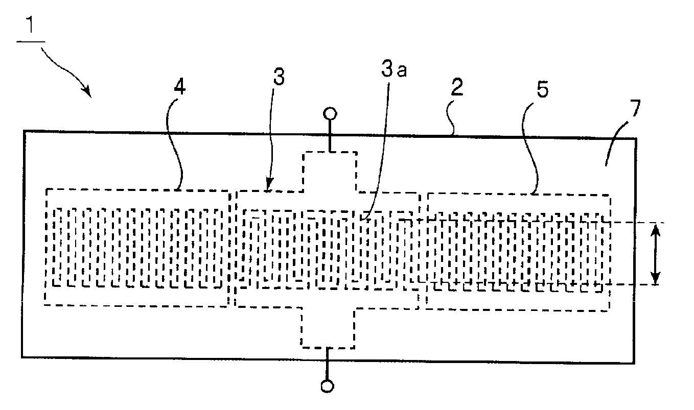
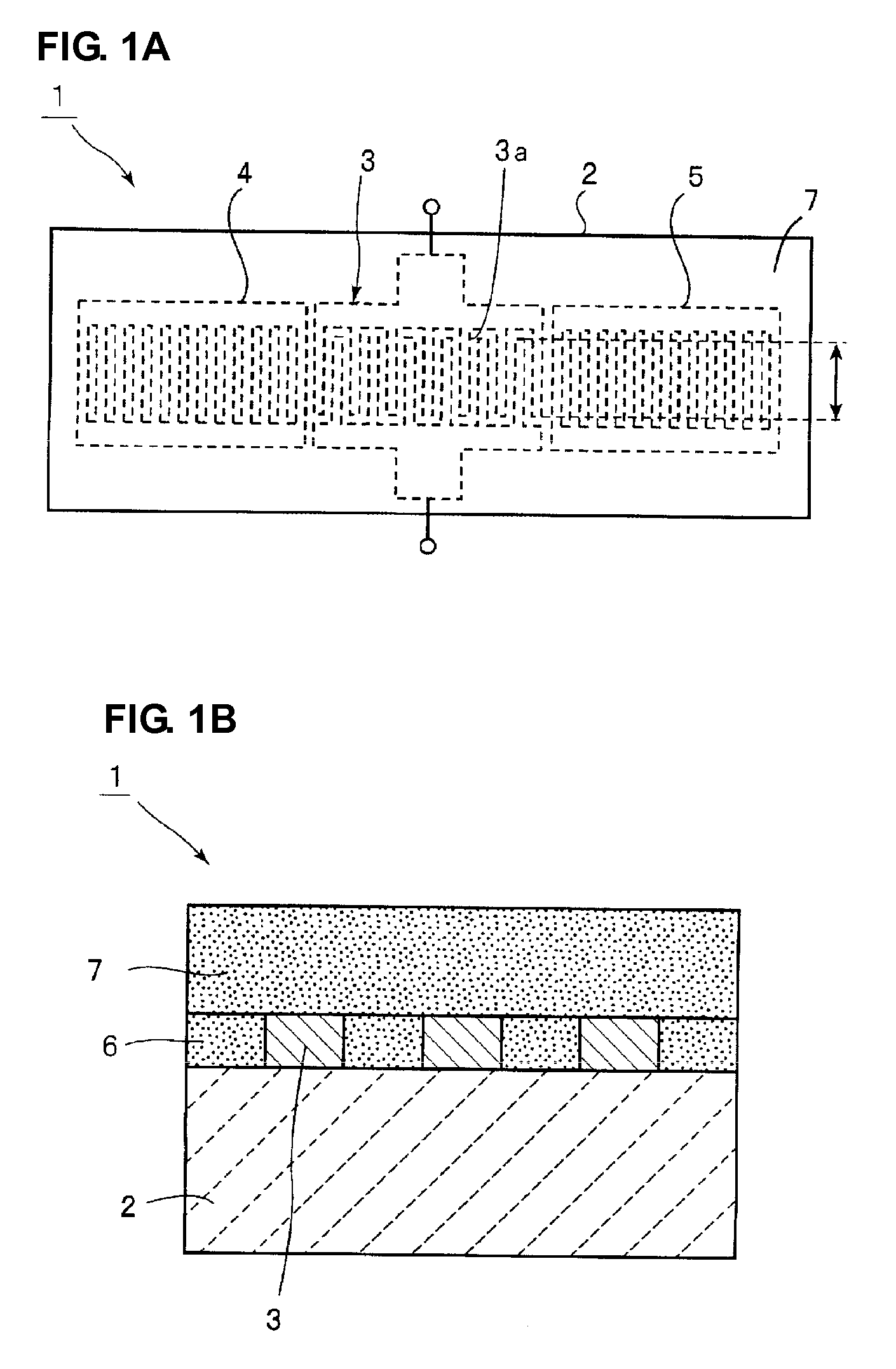
[0031]FIG. 1A is a schematic plan view of a surface acoustic wave device according to a preferred embodiment of the invention, and FIG. 1B is a partially enlarged front cross-sectional view that shows a relevant portion of the surface acoustic wave device.

[0032]The surface acoustic wave device 1 is preferably disposed of a Y-rotated X-propagating LiNbO3 substrate 2. The crystal orientation of the LiNbO3 substrate 2 is preferably (0°±5°, θ, 0°±10°) in Euler angles.

[0033]In addition, an IDT electrode 3 is disposed on the LiNbO3 substrate 2, as shown in FIG. 1B. As shown in FIG. 1A, reflectors 4 and 5 are disposed respectively on both sides of the IDT electrode 3 in a surface acoustic wave propagating direction in which a surface acoustic wave propagates.

[0034]In the remaining area other than these areas in which the e...


PUM


Abstract

A surface acoustic wave device has high power withstanding performance and is able to effectively suppress an undesirable spurious response. The surface acoustic wave device includes an LiNbO3 substrate having Euler angles (0°±5°, θ±5°, 0°±10°), an electrode that is disposed on the LiNbO3 substrate and that has an IDT electrode made mainly from Cu, a first silicon oxide film that is disposed in an area other than an area in which the electrode is disposed to have a thickness equal to that of the electrode, and a second silicon oxide film that is disposed so as to cover the electrode and the first silicon oxide film, wherein the surface acoustic wave device utilizes an SH wave, wherein a duty D of the IDT electrode is less than or equal to about 0.49, and θ of the Euler angles (0°±5°, θ±5°, 0°±10°) is set to fall within a range that satisfies the following inequality:
−10×D+92.5−100×C≦θ≦37.5×D2−57.75×D+104.075+5710×C2−1105.7×C+45.729
D: duty
C: thickness of the IDT electrode normalized using a wavelength λ.

Description

BACKGROUND OF THE INVENTION[0001]1. Field of the Invention[0002]The present invention relates to a surface acoustic wave device that is used, for example, as a resonator or a band-pass filter. More particularly, the present invention relates to a surface acoustic wave device that has a structure in which an IDT electrode and a silicon oxide film are disposed on a LiNbO3 substrate and that utilizes an SH wave.[0003]2. Description of the Related Art[0004]A band-pass filter used in an RF stage of a cellular phone, or the like, is required to have a wide band and an outstanding temperature characteristic. Thus, the existing art employs a surface acoustic wave device in which an IDT electrode is disposed on a piezoelectric substrate made of a Y-rotated X-propagating LiTaO3 substrate or a Y-rotated X propagating LiNbO3 substrate and a silicon oxide film is disposed to cover the IDT electrode. The piezoelectric substrate of this type has a negative frequency-temperature coefficient. Thus, ...

Claims


Application Information

Patent Timeline
Patent Type & Authority Applications(United States)
IPC IPC(8): H01L41/04
CPCH03H9/02559H03H9/14538H03H9/02834
Inventor NISHIYAMA, KENJINAKAO, TAKESHIKADOTA, MICHIO
Owner MURATA MFG CO LTD
Why Eureka
Try Eureka