High Temperature Superconducting Electromechanical System With Frequency Controlled Commutation For Rotor Excitation

a superconducting electromechanical system and rotor excitation technology, applied in the direction of superconductor details, motor/generator/converter stopper, dynamo-electric converter control, etc., can solve the problems of significant losses through the conductor extending across the interface, loss during power delivery from a 300 k environment, etc., to achieve low manufacturing cost, simple quench protection, and optimal heat load of the machine and efficiency

Inactive Publication Date: 2009-04-02
ADVANCED MAGNET LAB
View PDF35 Cites 15 Cited by
  • Summary
  • Abstract
  • Description
  • Claims
  • Application Information

AI Technical Summary

Benefits of technology

[0011]HTS machine designs which incorporate DH winding configurations and HTS flux pump transformers according to the invention permit high current, HTS persistent current mode operation for a rotor. This simplifies quench protection, which is of particular importance for superconducting windings based on HTS conductor. HTS splices required to form flux pump circuitry can remain superconducting to sustain a HTS persistive current mode. MgB2 is an exemplary HTS material with which these benefits can be achieved. With no current leads required between room and cryogenic temperature levels, heat loads of the machine and efficiency can be optimal.
[0012]Rotor windings and transformer coils formed with DH technologies offer unmatched mechanical robustness and electrical strength of the windings at low manufacturing costs. Unique stress management in the DH winding configuration enables high current densities in the superconductor, resulting in high air gap flux density and therefore high power density. For example, the DH winding technology enables coils capable of enduring large Lorentz forces due to their self-stabilizing, solenoidal configuration. Also, larger bending radii associated with DH geometries generates permit winding of brittle HTS materials in the manufacture of electrical machines. High rotor currents of several kA are possible, leading to reduced rotor inductance. Low rotor inductance facilitates current adjustments for synchronous condenser operation and also simplifies quench protection of the machine.

Problems solved by technology

Note, for example, losses occur during delivery of power from a 300 K environment to the superconducting windings.
HTS conductors differ from low temperature superconductors in that it is not possible to establish a true persistent current loop with an HTS conductor.
This is due to several factors including finite losses characteristic of HTS materials and characteristic resistive losses across splice junctions present in the circuitry.
Losses through the conductor extending across the interface are significant.

Method used


Image

  • High Temperature Superconducting Electromechanical System With Frequency Controlled Commutation For Rotor Excitation
  • High Temperature Superconducting Electromechanical System With Frequency Controlled Commutation For Rotor Excitation
  • High Temperature Superconducting Electromechanical System With Frequency Controlled Commutation For Rotor Excitation

Examples


Embodiment Construction

[0024]Before describing in detail the embodiments of a system and a method according to the invention, it is noted that the present invention resides primarily in a novel and non-obvious combination of components and process steps. So as not to obscure the disclosure with details that will be readily apparent to those skilled in the art, certain conventional components and steps have been omitted or presented with lesser detail, while the drawings and the specification provide greater emphasis on other elements and steps pertinent to understanding the invention. Further, the following embodiments do not define limits as to structure or method according to the invention, but provide examples which include features that are permissive rather than mandatory and illustrative rather than exhaustive.

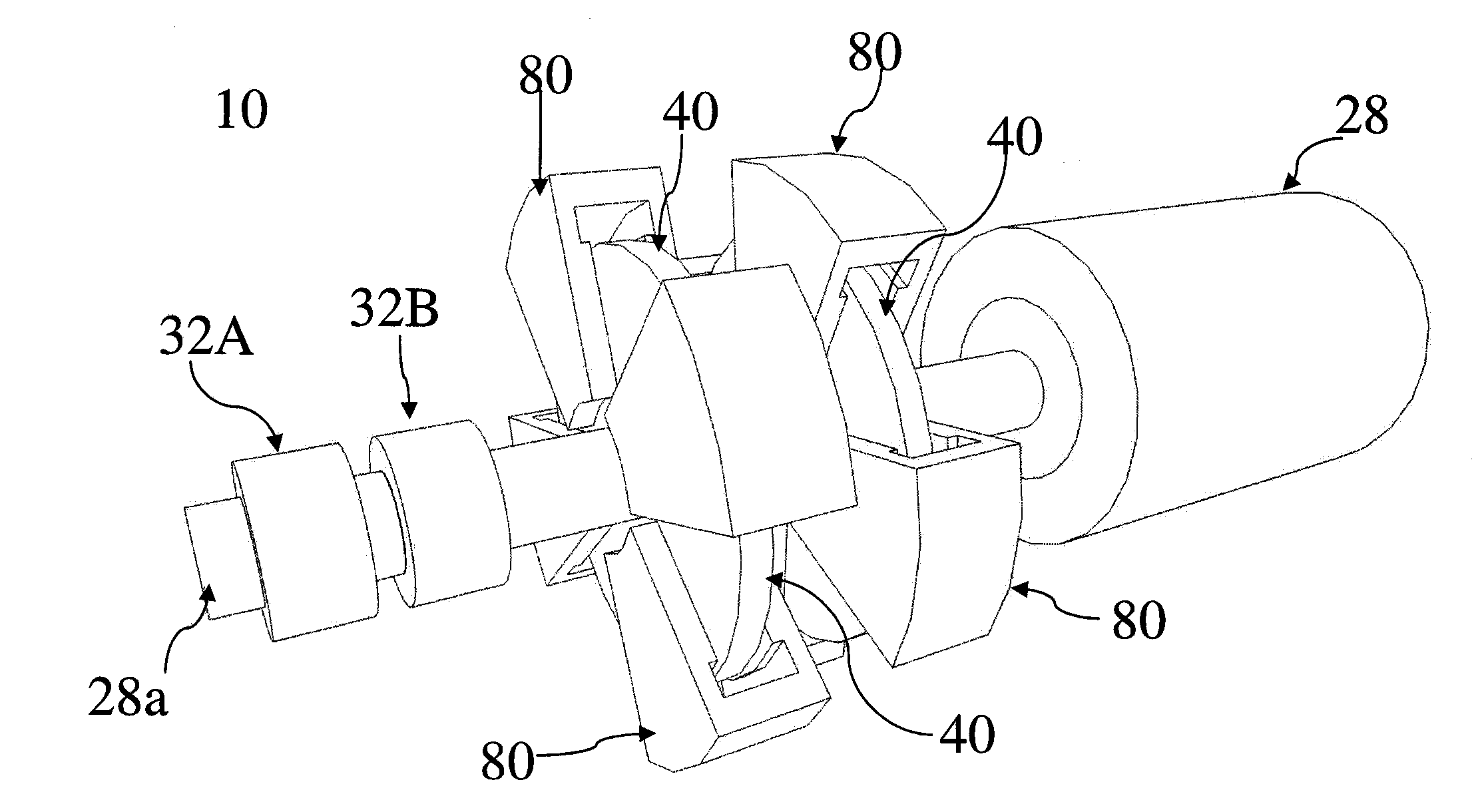
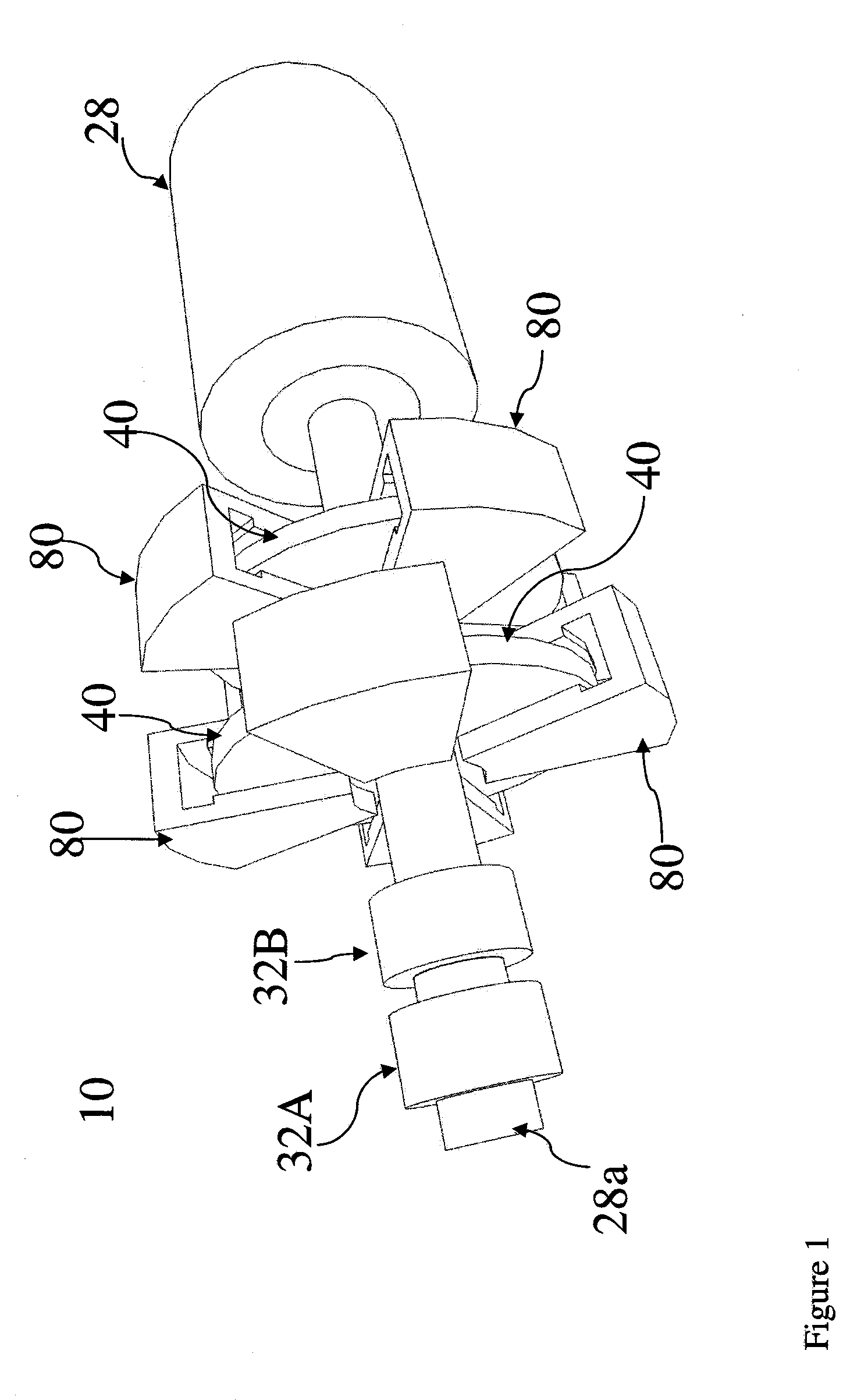
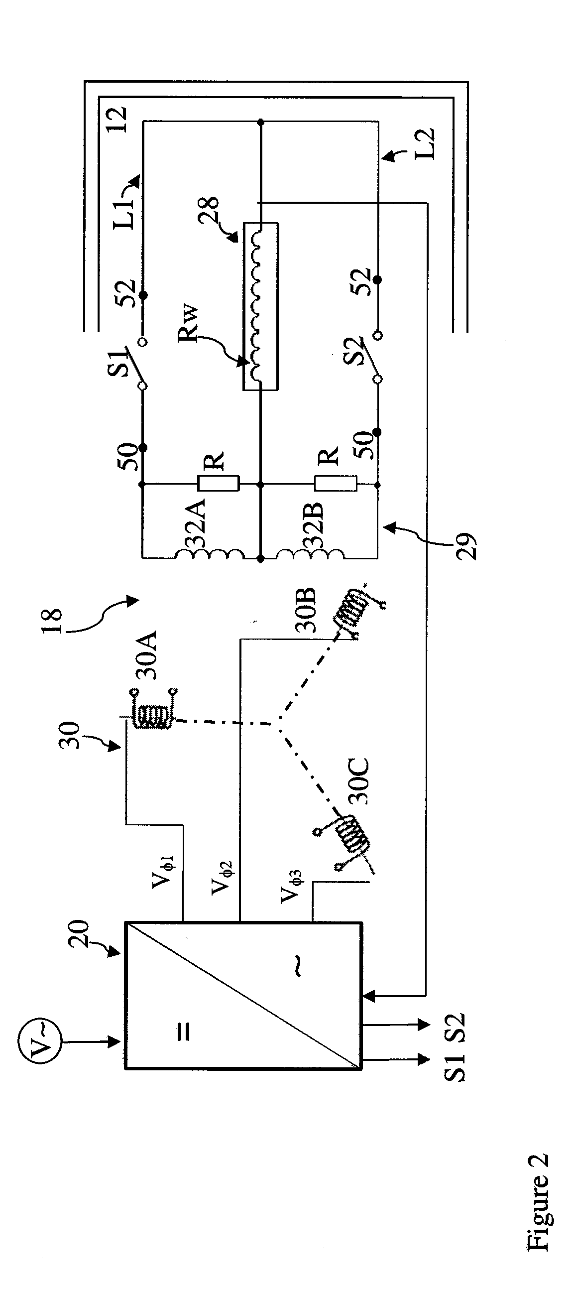
[0025]FIG. 1 is a simplified partial perspective view of a motor system 10 according to an example embodiment of the invention. FIG. 2 is an equivalent circuit illustrating features of a flux ...


PUM


Abstract

A system and method for generating a magnetic field in a rotating machine. In one embodiment, a primary winding assembly is configured to generate a rotatable magnetic field. The assembly is connected to receive multiple signals of different phases to effect field rotation. A set of secondary windings is positioned for generation of current based on magnetic coupling during the field rotation. The secondary windings include conductor capable of supporting superconducting current flow. A rotatable machine includes a stator and a rotor winding coupled for rotation with respect to the stator. The secondary windings are formed in a circuit for providing superconducting current through the rotor winding.

Description

RELATED APPLICATION[0001]This application claims priority to provisional patent application U.S. 60 / 968,591 filed 29 Aug. 2007 and provisional patent application U.S. 61 / 130,649, filed 2 Jun. 2008 which are each incorporated herein by reference in the entirety.FIELD OF THE INVENTION[0002]The invention relates to superconducting rotating machinery and, more particularly, to design and operation of machinery which incorporates a flux pump transformer to create a superconducting current in a winding thereof.BACKGROUND OF THE INVENTION[0003]There is a continuing desire to commercialize superconducting rotating machines because superconducting motor and generator operation can result in relatively high efficiencies above 99% and more than an order of magnitude very high specific power than conventional machines. Use of High Temperature Superconductor (HTS) materials, i.e., materials which exhibit superconduction at temperatures above 30 K, for superconducting machinery has been demonstra...

Claims


Application Information

Patent Timeline
Patent Type & Authority Applications(United States)
IPC IPC(8): H02P23/00H02K3/02
CPCH01F36/00H01F38/18H01L39/02Y02E40/66H02K19/36H02K55/04Y02E40/625H01L39/20Y02E40/60H10N60/80H10N60/355
Inventor MEINKE, RAINERMASSON, PHILIPPEISHMAEL, SASHA
Owner ADVANCED MAGNET LAB
Why Eureka
Try Eureka