Conductor Assembly Including A Flared Aperture Region

a technology of aperture region and conductor, applied in the field of electromagnetic systems, can solve the problems of charge particle, size, cost, and severe limit the availability of these applications, and achieve the effect of increasing the field

Inactive Publication Date: 2009-04-02
ADVANCED MAGNET LAB
View PDF10 Cites 30 Cited by
  • Summary
  • Abstract
  • Description
  • Claims
  • Application Information

AI Technical Summary

Benefits of technology

[0009]Many applications of magnets for charged particle beam optics can benefit from magnets that are curved. According to embodiments of the invention, this geometry can be implemented with pure multipole fields, i.e., predominantly one multipole order, by constructing double helix coil designs along curvilinear axes. A uniform magnetic dipole field can be applied to bend a charged particle beam trajectory into an arc. A magnet coil can be designed about a curved axis in order to avoid interference between the particle beam and the inner aperture of the magnet coil, e.g., a stainless steel vacuum tube. Simply transforming a double helix coil from a straight configuration, which generates a dipole field along a straight axis, into an arc of variable and arbitrary curv

Problems solved by technology

System size and cost severely limit the availability of these applications.
One impediment to further deployment of these and other charged particle beam systems is the size and cost of the beam acceleration and focusing equipment.
Moreover, the power demands of superconducting magnets are very low.
However, the opportunity to provide superconducting magnets in new applications may be compromised because of the well-known quenching phenomenon.
When the superconducting material undergoes an unexpected and rapid transition to a normal, non-superconducting state this can result in rapid formation of a high temperature hot spot which can destroy a magnet.
Designs which improve reliability have b

Method used


Image

  • Conductor Assembly Including A Flared Aperture Region
  • Conductor Assembly Including A Flared Aperture Region
  • Conductor Assembly Including A Flared Aperture Region

Examples


Embodiment Construction

[0034]Before describing in detail the particular methods and apparatuses related to embodiments of the invention, it is noted that the present invention resides primarily in a novel and non-obvious combination of components and process steps. So as not to obscure the disclosure with details that will be readily apparent to those skilled in the art, certain conventional components and steps have been omitted or presented with lesser detail, while the drawings and the specification describe in greater detail other elements and steps pertinent to understanding the invention. Further, the following embodiments do not define limits as to structure or method according to the invention, but provide examples which include features that are permissive rather than mandatory and illustrative rather than exhaustive.

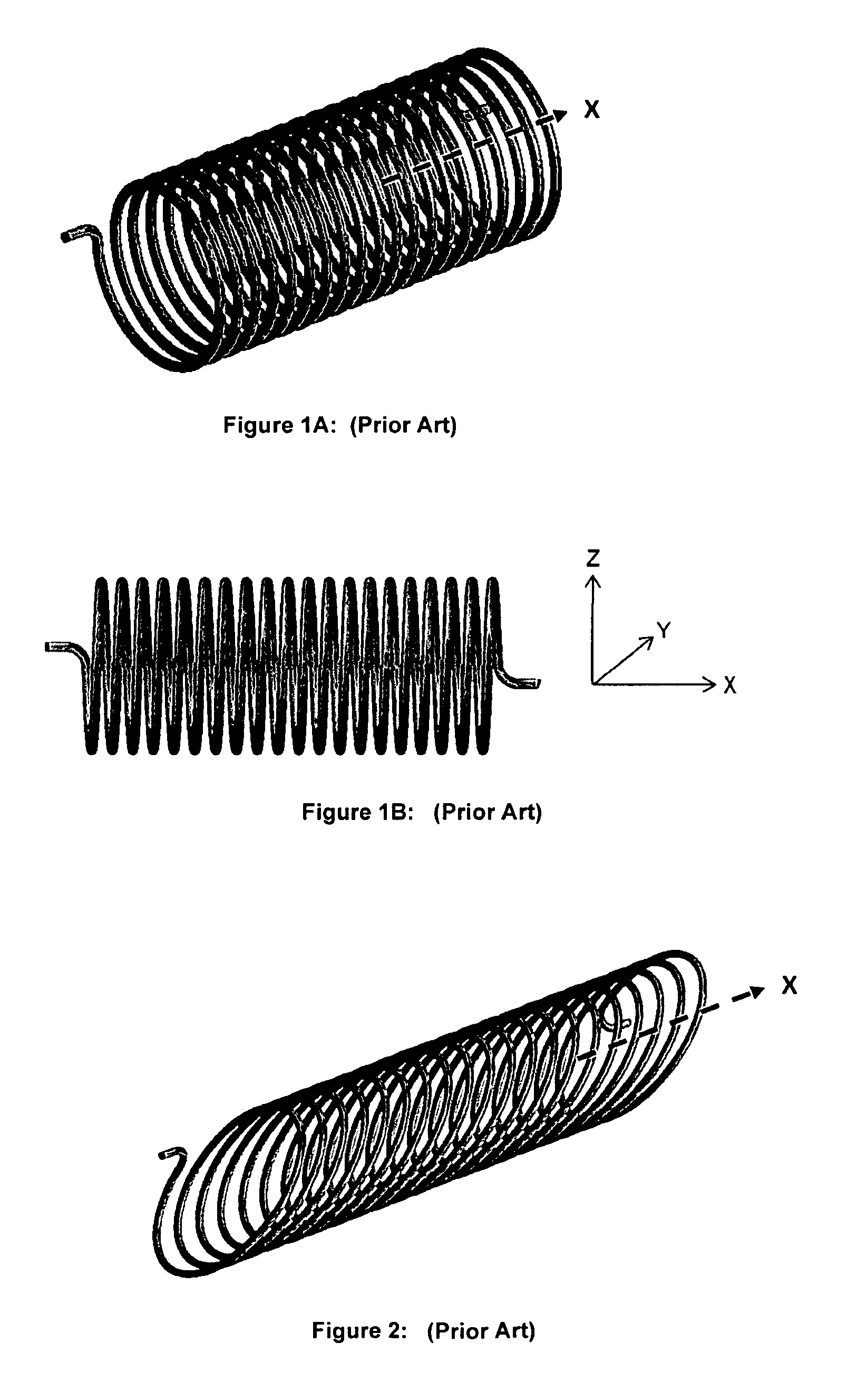
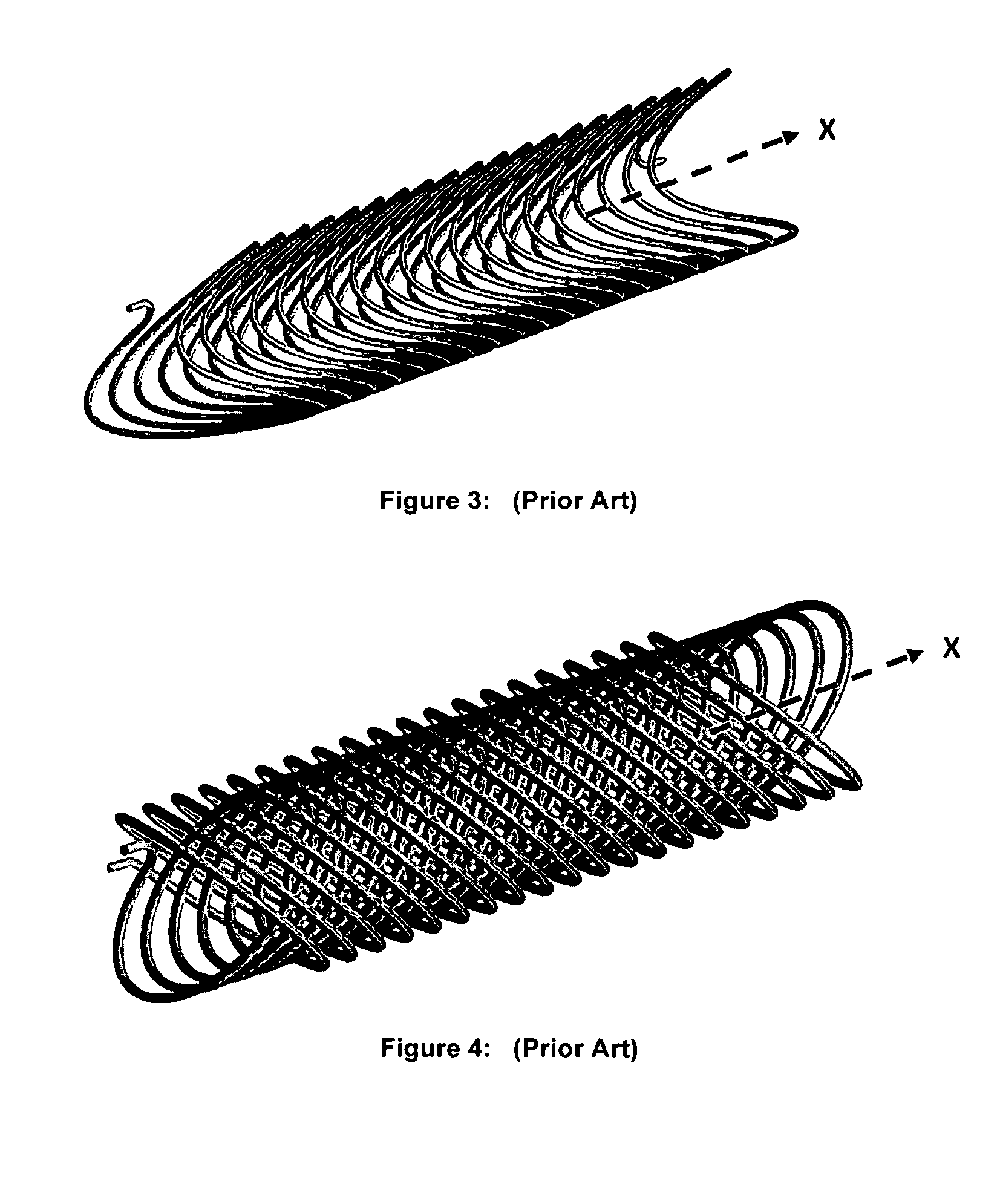
[0035]As used herein, the terms coil, spiral, helix and helical include but are not limited to regular geometric patterns. In addition, the terms coil, spiral and helix include confi...


PUM

PropertyMeasurementUnit
Angleaaaaaaaaaa
Magnetic fieldaaaaaaaaaa
Radiusaaaaaaaaaa

Abstract

A conductor assembly of the type which, when conducting current, generates a magnetic field or in which, in the presence of a changing magnetic field, a voltage is induced. A helical wiring pattern is positioned along an axis a radial distance R from the axis. The wiring pattern is formed about an aperture region extending from the axis toward the wiring pattern, the distance R varying along a portion of the axis.

Description

RELATED APPLICATION[0001]This application claims priority to provisional patent application U.S. 60 / 976,985 filed 2 Oct. 2007 which is incorporated herein by reference in the entirety.STATEMENT REGARDING FEDERALLY SPONSORED RESEARCH AND DEVELOPMENT[0002]The United States Government may have certain rights in this invention pursuant to U.S. Government Contract Number DE-FG02-06ER84492 awarded by the United States Department of Energy.FIELD OF THE INVENTION[0003]This invention relates to electromagnetic systems which generate magnetic fields. More particularly, the invention relates to systems of the type including conductor assemblies which, when conducting current, generate a magnetic field or which, in the presence of a changing magnetic field, generate or transform voltages.[0004]It is of continued importance across many sectors of the world economy (e.g., R&D, and medical applications) to achieve improved performance in magnetic conductor assemblies. Development of new and improv...

Claims


Application Information

Patent Timeline
IPC IPC(8): H01F27/28
CPCG01R33/34007G01R33/34046G01R33/34053G01R33/34084H01F6/02H01F6/06Y10T29/49071H01F41/065H01F41/0687Y10T29/4902Y10T29/49002Y10T29/49073H01F41/0641H01F5/00H01F5/02H01F7/202H01F27/323H01F41/048H01F2027/2833H05H7/04H01F41/064H01F41/071H01F41/086H01F41/098
Inventor MEINKE, RAINER
Owner ADVANCED MAGNET LAB
Why Eureka
Try Eureka