Driving apparatus, system and method thereof

Active Publication Date: 2009-04-02
NOVATEK MICROELECTRONICS CORP
View PDF4 Cites 4 Cited by
  • Summary
  • Abstract
  • Description
  • Claims
  • Application Information

AI Technical Summary

Benefits of technology

[0023]The present invention provides a method of reducing the spike current generated by the driving apparatus. The driving apparatus herein has a control switch disposed at the output terminal of the driving apparatus. The method includes following steps: first, generating a control signal; next, controlling the control switch located at the output terminal of the driving apparatus by using the control signal, wherein the control signal is used for controlling on or off of the control switch located at the output terminal of the driving apparatus and controlling the spike current generated as the control switch is turned on so as to lower down the spike current.
[0024]The present invention provides a method of reducing the spike current generated by the control switch. The control switch herein includes a control terminal, an input terminal and an output terminal. The control terminal is used for receiving the control signal. The method includes following steps: first, generating a control signal; next,

Problems solved by technology

However, a conventional driving apparatus applied to an LCD system would produce a huge spike current at a conductive moment, which may damage the chips and the panel of the LCD system due to the huge spike current.
However, when the rising speed and the falling speed of the above-mentioned switching signal TFT_open_sig are not ideal as expected, as a result, the analog driving signal may overwrite the image produced by the preceding analog driving signal of the liquid crystal unit 1032.
Although the above-described driving apparatus is able to avoid the problem t

Method used


Image

  • Driving apparatus, system and method thereof
  • Driving apparatus, system and method thereof
  • Driving apparatus, system and method thereof

Examples


Embodiment Construction

[0043]Reference will now be made in detail to the present preferred embodiments of the invention, examples of which are illustrated in the accompanying drawings. Wherever possible, the same reference numbers are used in the drawings and the description to refer to the same or like parts.

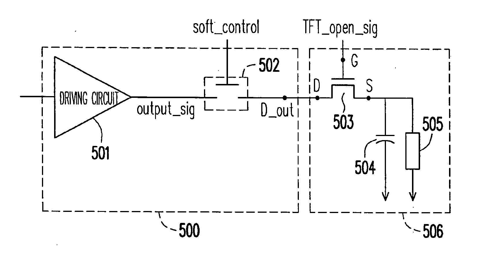
[0044]In order to solve the problem in the prior art that an excessive spike current may occur as the control switch in a conventional driving apparatus is turned on, the present invention adopts a soft start concept for controlling the control switch to lower down spike current, wherein the spike current generated as turning on or off the control switch is controlled by using a control signal so as to lower down the spike current.

[0045]FIG. 5 is a circuit diagram of a driving apparatus according to an embodiment of the present invention. Referring to FIG. 5, a driving apparatus 500 has at least an output terminal D_out, a driving circuit 501 and a control switch 502, wherein the control switch 502 i...


PUM


Abstract

A driving apparatus, a system and a method thereof is provided by the present invention. The driving apparatus has at least an output terminal and includes a driving circuit and a control switch. The control switch is electrically coupled with the driving circuit. The driving circuit receives an input signal and converts the input signal into an analog driving signal. The control switch is controlled by a control signal. When the control switch is turned on, the analog driving signal is able to be sent to the output terminal of the driving apparatus. The control signal further controls the spike current generated as turning on the control switch so as to reduce the spike current. The driving apparatus can be applied to an LCD system, so that the panel and the chips of the LCD system have longer life time, lower electricity consumption and better heat dissipation performance.

Description

CROSS-REFERENCE TO RELATED APPLICATION[0001]This application claims the priority benefit of Taiwan application serial no. 96136579, filed on Sep. 29, 2007. The entirety of the above-mentioned patent application is hereby incorporated by reference herein and made a part of specification.BACKGROUND OF THE INVENTION[0002]1. Field of the Invention[0003]The present invention generally relates to a driving apparatus and a method of reducing the spike current thereof, and more particularly, to a driving apparatus applied to an liquid crystal display system (LCD system) and a method of reducing the spike current thereof.[0004]2. Description of Related Art[0005]An LCD system includes a driving apparatus for converting an input signal into an analog driving signal so as make the LCD system display an image specified by the input signal. However, a conventional driving apparatus applied to an LCD system would produce a huge spike current at a conductive moment, which may damage the chips and t...

Claims


Application Information

Patent Timeline
IPC IPC(8): G09G3/36
CPCG09G3/3614G09G2330/025G09G3/3688
Inventor CHIU, WEI-TA
Owner NOVATEK MICROELECTRONICS CORP
Why Eureka
Try Eureka