
Interface module

a technology of interface modules and modules, applied in the field of interface modules, can solve the problems of complex manufacturing and management, unfavorable monolithic design, and affecting the quality of printed circuits, so as to reduce the number of products to be manufactured, simplify the coordination, and reduce the number of variants, in particular of the microcontrollers needed

Inactive Publication Date: 2009-04-02
ROBERT BOSCH GMBH
View PDF6 Cites 0 Cited by
  • Summary
  • Abstract
  • Description
  • Claims
  • Application Information

AI Technical Summary

Benefits of technology

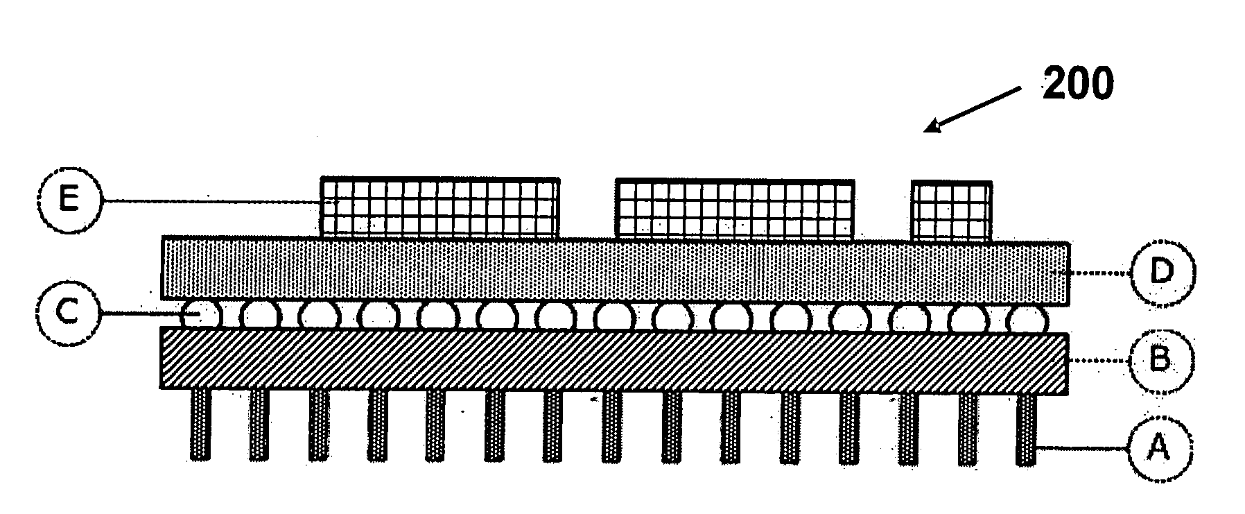
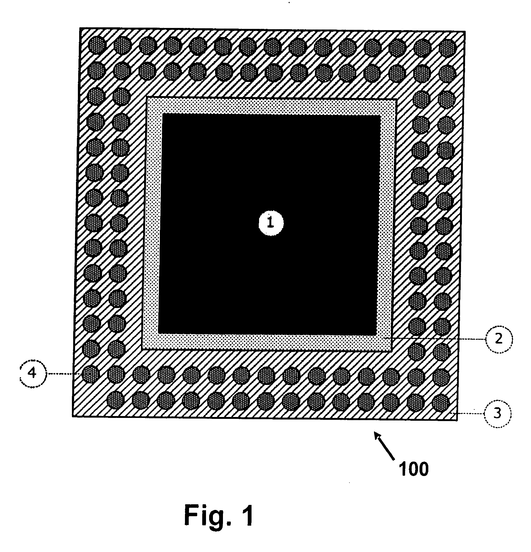
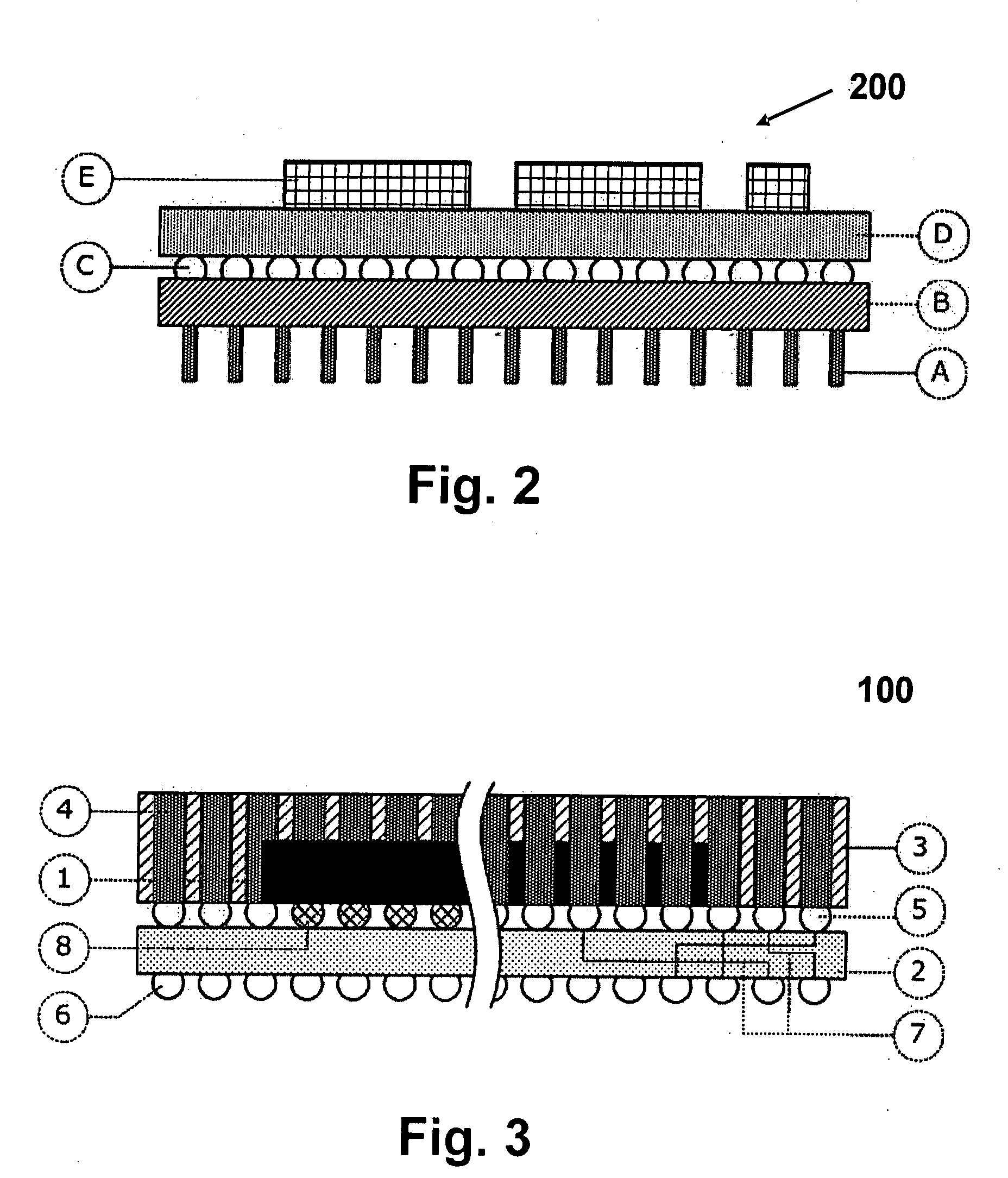
The present invention is about an interface module that can replace a component on a circuit board. The module is designed to be easily integrated into a base module using chip scale package technology. The integrated component can be a microcontroller or a memory module. The interface module has a smaller size than the original component, making it easier to adapt to different terminal variants. The interface module is connected to the base module and a tool access module using plug-in contacts and sockets. The integrated component can be a microcontroller or a memory module. The interface module simplifies the coordination between the tool manufacturer and the control unit manufacturer, as it has the same surface area as the original component. The physical separation between the adaptor part and the protocol converter part reduces the number of variants of microcontrollers needed and simplifies management and servicing. The modules are connected mechanically reliable and suitable for automobiles.

Problems solved by technology

This represents a disadvantage, since no high components should be situated on the control unit board under the interface module, i.e., the microcontroller interface.
This is difficult, since in particular in the starting phase of control unit development, the arrangement of the components may change considerably.
The monolithic design represents another disadvantage.
Therefore, a large number of interface module or interface variants results, which are complicated to manufacture and to manage.
It is apparent that the related art has not succeeded in delivering optimum results in all respects.

Method used


Image

  • Interface module
  • Interface module
  • Interface module

Examples


Embodiment Construction

[0027]According to the present invention, the microcontroller interface is considered as two logical parts:[0028]1) An adaptor part, which contacts the required input / output pins (I / O pins) of the microcontroller.[0029]2) A protocol converter, which converts MCU signals in such a way that they are reliably transmissible over longer distances.

[0030]In the related art, this is implemented in a monolithic design. The adaptor part and the protocol converter are inseparably implemented in a printed circuit. However, the adaptor part is dependent on the mechanical design (e.g., housing) and on the type of the microcontroller, while the protocol converter depends on the activity performed. A high number of interface variants result in this way in the related art, which are costly to manufacture and manage. This disadvantage is eliminated and the system is improved by the physical separation according to the present invention into an adaptor part as a base module (100) and a protocol conver...


PUM


Abstract

An interface module has an integrated component for replacing a component on a circuit board, the terminal contacts on the bottom side of the interface module being designed as provided for the contacts of the component on the circuit board, the interface module being divided into an adaptor part as a base module and a protocol converter part as a tool access module.

Description

FIELD OF THE INVENTION[0001]The present invention is directed to an interface module having an integrated component.BACKGROUND INFORMATION[0002]Such interface modules are used in different applications. One possibility is, for example, to replace a memory module of a control unit with such an interface module having an integrated component. The actual memory module, for example, an EPROM, EEPROM, flash memory, RAM, etc., is replaced by an interface module having an emulator memory, e.g., via an emulator probe. Such an interface module may also be referred to as a memory interface. This memory interface makes it possible to access memory data of a control unit using a software tool via an external device known as a tool computer (e.g., a PC) and execute measuring and calibration applications on the control unit.[0003]However, microcontrollers of a control unit itself may also be replaced by this interface module having an integrated component, in which case the component is a microco...

Claims


Application Information

Patent Timeline
Patent Type & Authority Applications(United States)
IPC IPC(8): H05K1/18
CPCH01L23/49827H05K2203/176H01L2224/16H01L2924/01078H01L2924/01079H01L2924/15311H01L2924/15312H05K1/141H05K1/144H05K3/225H05K3/3436H05K2201/049H05K2201/10325H05K2201/10734H01L23/49838H01L2924/00014H01L2924/00011H01L2224/0401H05K1/14H05K3/30G06F13/00G06F1/00
Inventor MOESSNER, CLAUSTRIESS, BURKHARDMAIER, GERTBACH, PETER
Owner ROBERT BOSCH GMBH
Learn More