Fiber ring laser

a fiber ring laser and fiber technology, applied in the direction of lasers using scattering effects, laser details, electrical equipment, etc., can solve the problems of increasing the cost of dual-wavelength lasers, aggregating nonlinear effects, and high cost of fiber communication components, so as to reduce manufacturing costs and further reduce manufacturing costs

Inactive Publication Date: 2009-04-02
IND TECH RES INST
View PDF2 Cites 11 Cited by
  • Summary
  • Abstract
  • Description
  • Claims
  • Application Information

AI Technical Summary

Benefits of technology

[0020]The fiber ring laser of an exemplary embodiment of the present invention mainly adopts a fiber ring and a optic amplifier to generate resonant cavities and amplify the resonance signals, so as to generate a laser beam with more than two wavelengths. Based on the above architecture, an exemplary example consistent with the present invention does not need a passive optical filter, thus reducing the manufacturing cost. The fiber ring laser of the present invention does not need a high-power pumping laser, which is different from the conventional multi-wavelength or dual-wavelength laser using the Raman amplifier, so the manufacturing cost can be further reduced.

Problems solved by technology

However, the fiber communication components are quite expensive due to the complex processes or the materials, so the communication technology is mainly used in the backbone network.
The precise FBG requires a fine coating technique, thus raising the cost of the dual-wavelength laser.
However, the multi-wavelength laser needs a Raman resonator, which aggregates the nonlinear effect of the overall laser.
Therefore, an expensive high-power pumping laser must be added.
The multi-wavelength laser needs a precise FBG and expensive high-power pumping laser, thus leading to a high manufacturing cost of the multi-wavelength laser.
1387-1389”, Bakhshi et al. set forth a dual-wavelength laser that needs two Raman pumping lasers and requires a complex mode-locking circuit, so the cost is till high.
Therefore, the dual-wavelength laser provided by Xueming Liu still has the problem of the cost.
Therefore, the cost of the conventional multi-wavelength or dual-wavelength laser is high.

Method used


Image

  • Fiber ring laser
  • Fiber ring laser
  • Fiber ring laser

Examples


Embodiment Construction

[0031]The present invention provides a fiber ring laser, which is capable of emitting a laser beam with more than two wavelengths without using a passive optical filter in the fiber ring or relying on the nonlinear effect (for example, Raman amplifier).

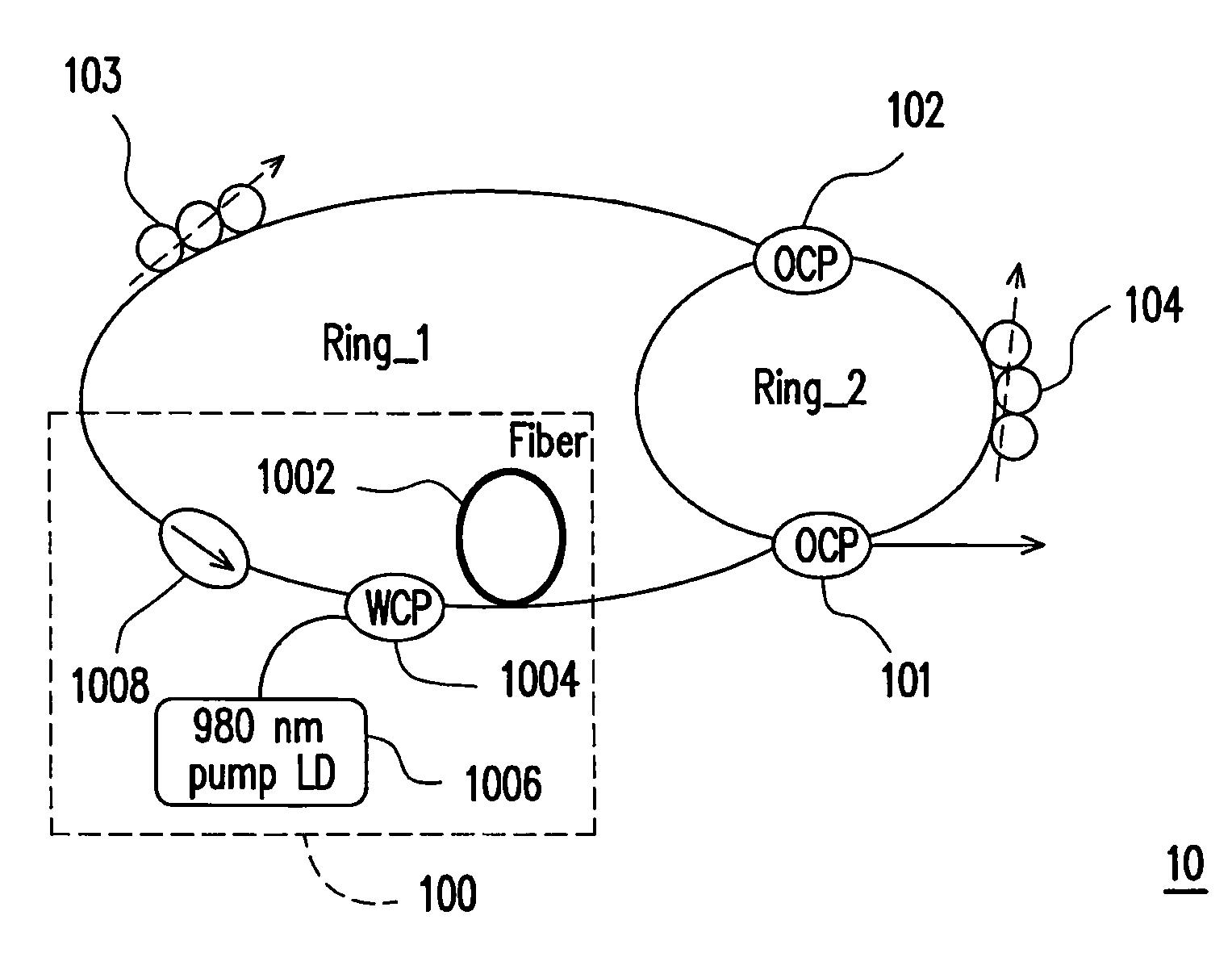
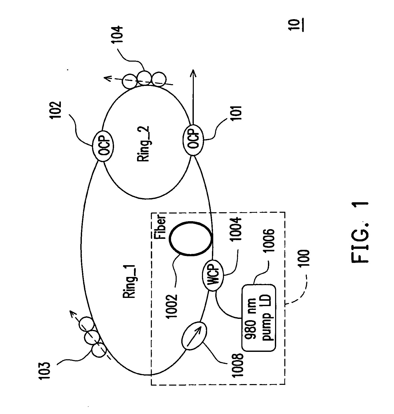
[0032]The present invention mainly uses an optic amplifier and fiber rings to form resonant cavities, so as to generate a laser beam with more than two wavelengths. Referring to FIG. 1, a fiber ring laser according to an embodiment of the present invention is shown. A fiber ring laser 10 includes an optic amplifier 100, a first OCP 101, a second OCP 102, a first fiber ring Ring_1, a second fiber ring Ring_2, a first PC 103, and a second PC 104. The first fiber ring Ring_1 is coupled to the optic amplifier 100, the first and the second OCP 101, 102. The second fiber ring Ring_2 is coupled to the first and the second OCP 101, 102. The first PC 103 is coupled to the first fiber ring Ring_1. The second PC 104 is coupled to the second fibe...


PUM


Abstract

A fiber ring laser is provided, which includes an optic amplifier, a first optical coupler (OCP), a second OCP, a first fiber ring, a second fiber ring, a first polarization controller (PC), and a second PC. The first fiber ring is coupled to the optic amplifier, the first and the second OCPs. The second fiber ring is coupled to the first and the second OCPs. The optic amplifier amplifies a first laser beam with a specified wavelength range. The first fiber ring receives the first laser beam. The first and the second fiber rings respectively provide a first and a second resonant cavities. The first and the second PCs respectively control polarization states of the first and second resonant cavities. The first laser beam resonates in the first and the second resonant cavities to generate a second laser beam with a first and a second wavelengths.

Description

CROSS-REFERENCE TO RELATED APPLICATION[0001]This application claims the priority benefit of Taiwan application serial no. 96136902, filed on Oct. 2, 2007. The entirety of the above-mentioned patent application is hereby incorporated by reference herein and made a part of this specification.BACKGROUND OF THE INVENTION[0002]1. Field of the Invention[0003]The present invention relates to a fiber ring laser, and more particularly, to a fiber ring laser capable of emitting a laser beam with multiple wavelengths.[0004]2. Description of Related Art[0005]Fiber communication technology provides an extremely wide bandwidth, which facilitates the users to enjoy rapid and convenient network service. However, the fiber communication components are quite expensive due to the complex processes or the materials, so the communication technology is mainly used in the backbone network. Currently, the methods of division multiplexing in the fiber communication technology include time division multiplex...

Claims


Application Information

Patent Timeline
Patent Type & Authority Applications(United States)
IPC IPC(8): H01S3/092
CPCH01S3/06712H01S3/06791H01S3/1608H01S3/082H01S3/0809
Inventor CHI, SIENYEH, CHIEN-HUNG
Owner IND TECH RES INST
Why Eureka
Try Eureka