Eureka AIR delivers breakthrough ideas for toughest innovation challenges, trusted by R&D personnel around the world.

Enhancement for navigation systems for using weather information when predicting a quickest travel path

Inactive Publication Date: 2009-04-02
IBM CORP
View PDF2 Cites 58 Cited by
  • Summary
  • Abstract
  • Description
  • Claims
  • Application Information

AI Technical Summary

Benefits of technology

[0007]The present invention discloses a software service that uses weather forecasts and historical information concerning travel paths and their traversal times in various weather conditions to determine a travel path having a shortest estimated time in light of weather conditions. The software service can he part of a navigation system and / or can be integrated into a mapping software program. For example, a GPS equipped in-vehicle navigation system using the disclosed solution can compute a best driving path based upon predicted weather conditions. In another example, a mapping service, such as MAPQUEST, can provide improved results using the disclosed solution by considering predicted weather conditions when mapping a travel pathway from a source to a destination. In one embodiment, period updates can be obtained from a weather service, which can cause weather forecasts to change, which in turn can cause a suggested travel pathway to dynamically change, in another embodiment, navigation systems equipped to utilize weather forecasts can provide data concerning actual driving times and actual weather conditions, which can be used to populate the historic data and to otherwise establish a training feedback loop.

Problems solved by technology

What often happens is that once delays occur, a driver is stuck in a traffic jam with no ability to maneuver around it to get to an alternate route.
Choices of alternative routes and resultant delays often vary directly in proportion to a drivers distance from a traffic flow problem.
As the distance to the traffic flow problem decreases, alternative route delay times generally increase.

Method used


Image

  • Enhancement for navigation systems for using weather information when predicting a quickest travel path
  • Enhancement for navigation systems for using weather information when predicting a quickest travel path
  • Enhancement for navigation systems for using weather information when predicting a quickest travel path

Examples


Embodiment Construction

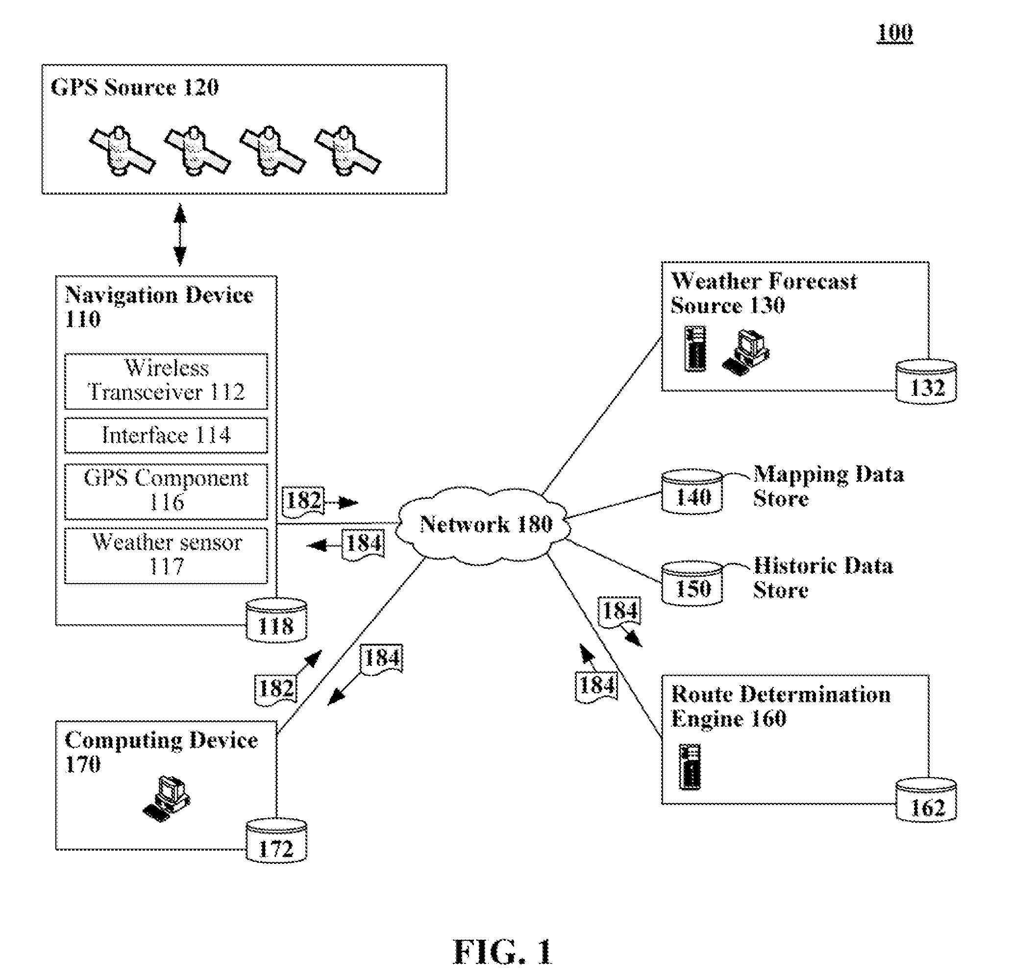
[0016]FIG. 1 is a schematic diagram of a system 100 in which travel path determinations are made based at least in part upon forecasted weather conditions. In system 100, a navigation device 110 or a computing device 170 conveys a travel request 182 to a travel path determination engine 160. Prom the request 182, the engine 160 can determine a point of origin, a destination, and a travel time. The travel path determination engine 160 can then use mapping data from mapping data store 140 to determine a multiple connectivity paths (N paths) for traveling from the point of origin to the destination. The engine 160 can then access weather forecast source 130 to determine predicted weather along each of the N travel paths for the estimated travel times. A historical data store 150 can be queried, which contains historic traffic flow data for different travel pathways and pathway portions given different weather conditions. An estimated time of travel for a given weather condition (i.e., ...


PUM


Abstract

The present invention discloses a software method for determining a travel path. The software method can identify a point of origin, a travel destination, and a travel time. Multiple different possible travel pathways between the point of origin and the travel destination can be determined. Predicted weather conditions for each of the travel pathways for a time of travel can be ascertained. Time estimates for each of the travel pathways can be adjusted based on the predicated weather conditions for each of the travel pathways. At least one of the determined travel pathways can be presented based at least in part upon the time estimates that have been adjusted for the predicted weather conditions and historical data about the given pathways with similar weather to that which is being predicted. In one embodiment; the software method can be performed by a Global Positioning System (GPS) equipped motor vehicle navigation system.

Description

BACKGROUND[0001]1. Field of the Invention[0002]The present invention relates to navigation systems and travel path software solutions, and more particularly; to an enhancement for navigation systems for using weather information when predicting a quickest travel path.[0003]2. Description of the Related Art[0004]The global positioning system (GPS) is a fully functional global navigation satellite system (GNSS). The system utilizes at least twenty four medium Earth orbit satellites that transmit microwave signals to allow a GPS receiver to determine its location, speed, and direction. The GPS system is maintained by the government and is provided free for civilians. A very common use of the GPS system is for navigation. Consumers often buy GPS receivers and use them in their cars. Locations can he entered using the GPS receiver and the receiver can plot a course to the desired destination. The GPS receiver can then display appropriate maps and directions to direct the consumer to thei...

Claims


Application Information

Patent Timeline
IPC IPC(8): G01C21/34
CPCG01C21/3492
Inventor BURCKART, ERIK J.IVORY, ANDREW J.SHEARD, MATTHEW J.SHOOK, AARON K.
Owner IBM CORP
Why Eureka
Eureka Blog
Learn More