Gyroscope
a gyroscope, high-performance technology, applied in the direction of acceleration measurement using interia force, turn-sensitive devices, instruments, etc., can solve the problems of inability to obtain stability, limited proof mass velocity, sensitivity and stability decline, etc., to achieve stable performance, high performance and stability, the effect of easy manufacturing
- Summary
- Abstract
- Description
- Claims
- Application Information
AI Technical Summary
Benefits of technology
Problems solved by technology
Method used
Image

Examples
first embodiment
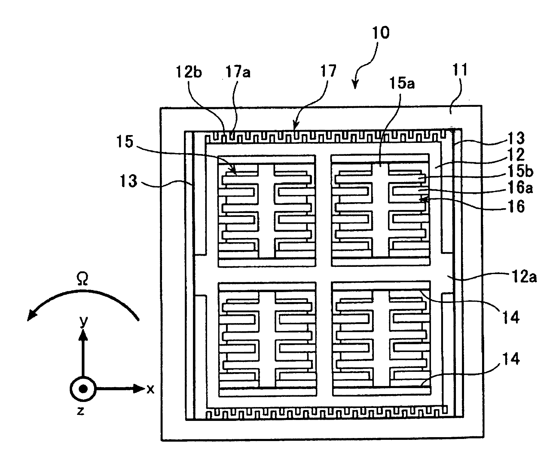
[0066]FIG. 4 is a schematic plane view of a gyroscope 10 having four proof masses 15 according to the present invention. The gyroscope 10 is made from An SOI (Silicon on Insulator) substrate which includes a silicon oxide film and two silicon substrates on both sides thereof. The gyroscope 10 comprises an outer frame 11 which has a square cross section, and an inner frame 12 which is positioned inside the outer frame 11 and which has a square cross section. Center portions 12a of two sides in x-direction of the inner frame 12 are connected to the insides of the outer frame 11 by two outer support suspensions 13 which are parallel to y-axis. The outer support suspensions 13 are plate shaped members having thin thickness. One end of each of the outer support suspensions 13 is connected to a corresponding inner side of the outer frame 11, and the other end of each of the outer support suspensions 13 is connected to a corresponding one of the center portions 12a of the inner frame 12, a...
second embodiment
[0104]FIG. 8—A schematic plane view of the gyroscope having proof masses positioned in a circle according to the present invention.
[0105]FIG. 9—Schematic plane views and cross sectional views showing steps for making the gyroscope of the embodiments of the present invention.
[0106]FIG. 10—A perspective view showing the structure of the gyroscope made from an SOI substrate.
[0107]FIG. 11—A cross sectional view of an embodiment in which the proof masses have metal layers.
PUM
 Abstract
Description
Claims
Application Information
 - R&D
- Intellectual Property
- Life Sciences
- Materials
- Tech Scout
- Unparalleled Data Quality
- Higher Quality Content
- 60% Fewer Hallucinations
Browse by: Latest US Patents, China's latest patents, Technical Efficacy Thesaurus, Application Domain, Technology Topic, Popular Technical Reports.
© 2025 PatSnap. All rights reserved.Legal|Privacy policy|Modern Slavery Act Transparency Statement|Sitemap|About US| Contact US: help@patsnap.com