

Optical compensation film, polarizing plate, and liquid-crystal display device
a liquid crystal display device and optical compensation technology, applied in the field of optical compensation films and liquid crystal display devices, can solve the problems of yellowish panel that should be white, unsatisfactory viewing angle characteristics of conventional pc display monitors, etc., and achieve the effect of improving the viewing angle characteristics of liquid crystal display devices and reducing yellow color shi
- Summary
- Abstract
- Description
- Claims
- Application Information
AI Technical Summary
Benefits of technology
Problems solved by technology
Method used
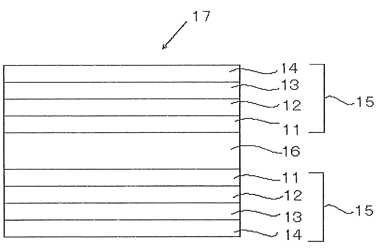
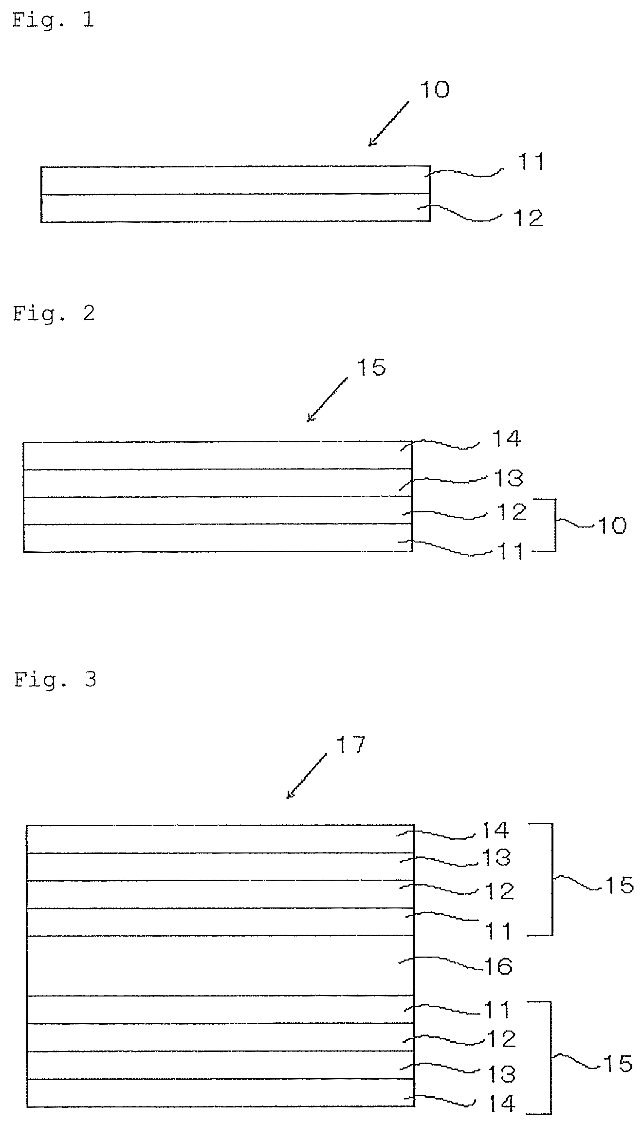
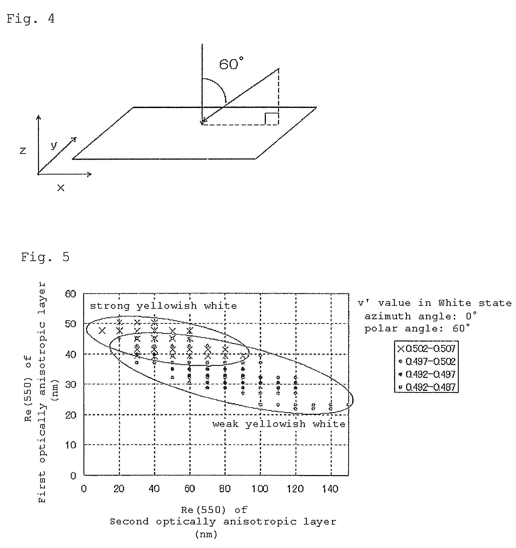
Image

Examples
example 1
(Formation of Second Optically-Anisotropic Layer (Cellulose Acylate Film 1))
[0206]The ingredients shown in the following Table were mixed to prepare a cellulose acylate solution. The cellulose acylate solution was cast on a metal support, and the formed web was peeled away from the support, and stretched in TD direction by 20% at 185° C. to produce a cellulose acylate film 1. TD direction means the direction perpendicular to the film traveling direction. After stretched, the thickness of the film was 80 μm.
IngredientCellulose acylate having a degree of acetyl substitution of 2.94100 mas. pts.Triphenyl phosphate 3 mas. pts.Biphenyl phosphate 2 mas. pts.Retardation-controlling agent (1) 5 mas. pts.Retardation-controlling agent (2) 2 mas. pts.Methylene chloride644 mas. pts.Methanol 56 mas. pts.Retardation-Controlling Agent (1):Retardation-Controlling Agent (2):
[0207]Re(550) of the cellulose acylate film 1 obtained in the above was 80 nm, and Rth(550) thereof was 60 nm.
(Formation of Ali...
example 2
(Formation of Second Optically-Anisotropic Layer (Cellulose Acylate Film 2))
[0218]A cellulose acylate film (TAC-TD80U, by FUJIFILM) was stretched in TD direction by 20% at 240° C. to prepare Cellulose acylate film 2. The thickness of the stretched film was 80 μm.
[0219]Re(550) of Cellulose acylate film 2 was 60 nm, and Re(550) thereof was 60 nm.
[0220]In the same manner as in Example 1, an alignment film and a first optically-anisotropic layer were formed, thereby fabricating Optical compensation film 2 and Polarizing plate 2; and using Polarizing plate 2 and in the same manner as in Example 1, TN-mode liquid-crystal display device 2 was constructed.
example 3
[0235]An optical compensation film, a polarizing plate and a TN-mode liquid-crystal display device were produced in the same manner as in Example 1, for which, however, a cyclic polyolefin film produced according to the method described below was used as the second optically-anisotropic layer (Re(550)=80 nm, Rth(550)=60 nm). The test results of the device were also excellent like those of TN-mode liquid-crystal display device 1 produced in Example 1.
(Preparation of Ring-Opening Polymerized Cyclic Polyolefin)
[0236]The following composition was put into a mixing tank and stirred to dissolve the ingredients, and then the solution was filtered through a filter paper having a mean pore size of 34 μm and a sintered metal filer having a mean pore size of 10 μm.
Cyclic Polyolefin Solution AArton G (by JSR)150mas. pts.Methylene chloride550mas. pts.Ethanol50mas. pts.
[0237]Next, the following composition containing the ring-opening polymerized cyclic polyolefin solution prepared according to th...
PUM
| Property | Measurement | Unit |
|---|---|---|
| wavelength | aaaaa | aaaaa |
| wavelength | aaaaa | aaaaa |
| wavelength | aaaaa | aaaaa |
Abstract
Description
Claims
Application Information