

Method and apparatus for performing surface treatment of rubber member
- Summary
- Abstract
- Description
- Claims
- Application Information
AI Technical Summary
Benefits of technology
Problems solved by technology
Method used
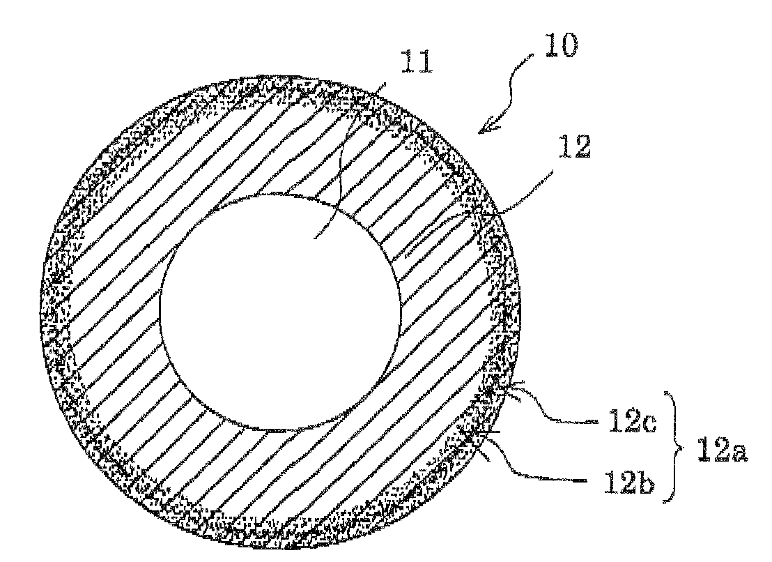
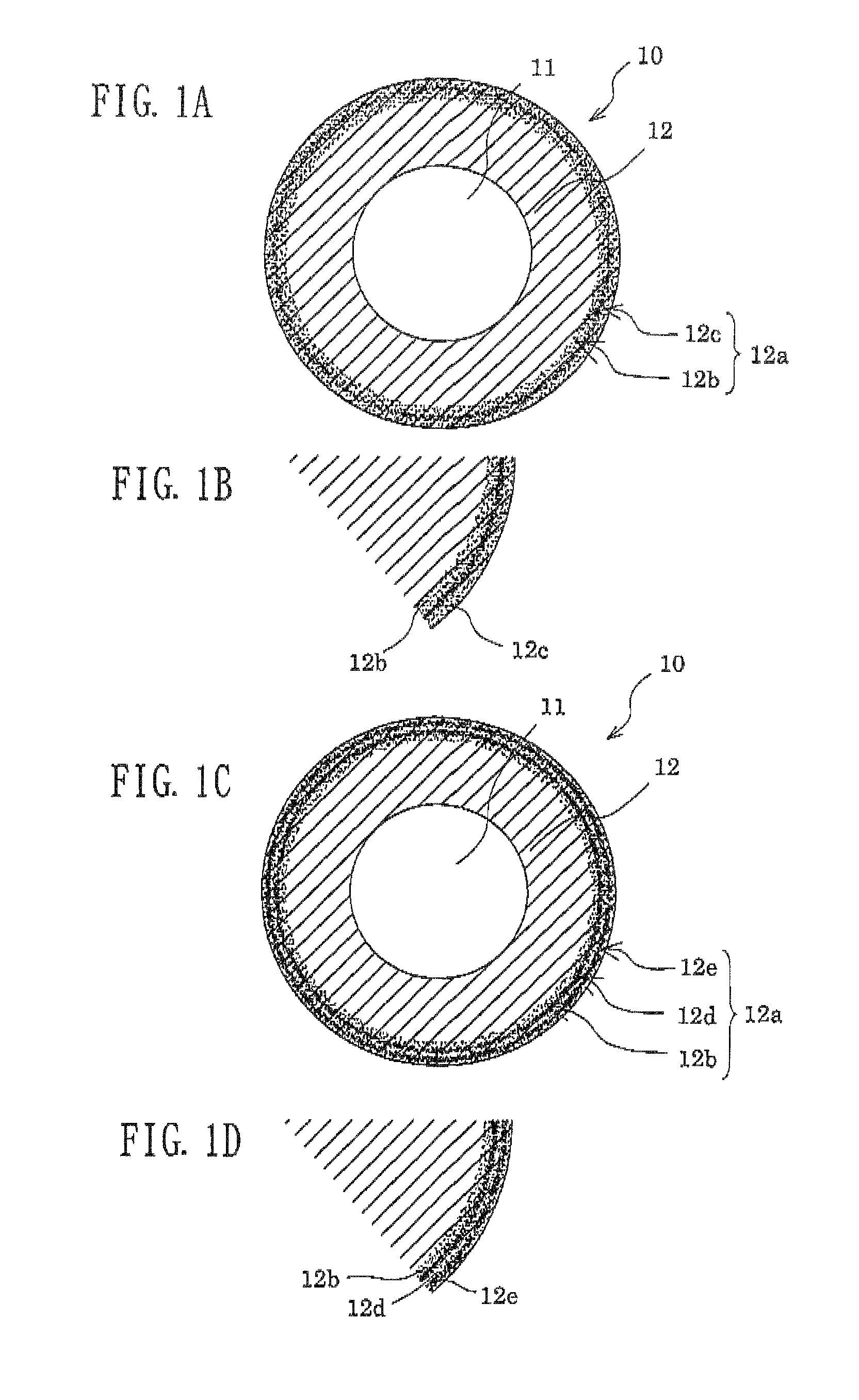
Image

Examples
embodiment 1
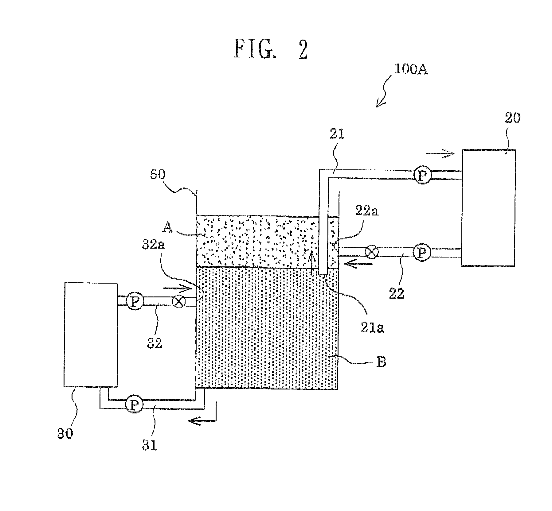
[0068]FIG. 2 is a cross-sectional view of surface treatment apparatus for a rubber member of Embodiment 1.
[0069]A container 50 of the surface treatment apparatus for a rubber member has a shape of, for example, a hollow cylinder or a hollow polygonal prism and, during use, receives a first surface-treatment liquid containing an isocyanate component and an organic solvent, and a second surface-treatment liquid which is separated from the first liquid, in a phase-separated two-layer state.
[0070]The container 50 is equipped with a discharge tube 21 for discharging a surface-treatment liquid forming an upper liquid layer A, and an outlet 21a of the discharge tube 21 is disposed below the interface between the upper liquid layer A and a lower liquid layer B. The discharge tube 21 is formed of a plurality of cylindrical pipes so that the discharge tube 21 can stretch and contract so as to dispose the outlet 21a below the liquid surface of the liquid layer B fed to the container 50.
[0071]T...
embodiment 2
[0091]FIG. 6 is a cross-sectional view of surface treatment apparatus for a rubber member according to Embodiment 2 of the invention. The same reference numerals as employed in Embodiment 1 are denoted by the same reference numerals, and repeated descriptions are omitted.
[0092]A container 50, which serves as a main body of surface treatment apparatus for a rubber member, has a separator plate 51 extending upward from the bottom of the container 50 to a certain height which is lower than the height of the container, which allows two liquid layers to be received in a lower section of the container. The separator plate 51 is provided for dividing the lower section of the container 50. No particular limitation is imposed on the separator plate, so long as the plate can regulate transfer of the liquids. The container 50 can receive the lower liquid layer B and a lower liquid layer C in a separated state and the upper liquid layer A in an upper section. The interface between the upper liq...
example 1
[0111]Ketjen Black EC (product of Ketjen Black International) (3 parts) and Asahi #60 (product of Asahi Carbon) (5 parts) were added to 3-functional polyether polyol (MN-3050, product of Mitsui Takeda Chemical) (100 parts), and carbon particles were dispersed to a particle size of about 20 μm or less, followed by maintaining at 80° C., and defoaming and dehydrating for 6 hours under reduced pressure, to thereby prepare liquid A. Separately, Coronate C-HX (product of Nippon Polyurethane industry Co., Ltd.) (10 parts) was added to a prepolymer (Adiprene L100, product of Uniroyal) (22 parts), and the mixture was maintained at 80° C., to thereby prepare liquid B. Liquids A and B were mixed, and the mixture was poured into a metal mold (iron pipe, φ: 23 mm) in which a shaft (φ: 8 mm, l: 270 mm) had been inserted along the center axis and which had been heated at 120° C. The mixture was molded at 120° C. for 120 minutes, to thereby produce a roller having a conductive polyurethane layer o...
PUM
| Property | Measurement | Unit |
|---|---|---|
| Fraction | aaaaa | aaaaa |
| Electrical conductivity | aaaaa | aaaaa |
| Polarity | aaaaa | aaaaa |
Abstract
Description
Claims
Application Information