Centrifugally cast composit roll

a technology of centrifugal casting and composite rolls, which is applied in the direction of manufacturing tools, transportation and packaging, and power-driven tools. it can solve the problems of deteriorating dimensional precision of rolled products, premature wear of surfaces, and deteriorating work appearance, and achieve excellent spalling resistance, surface roughening resistance and seizure resistance, excellent wear resistan

Inactive Publication Date: 2009-04-09
HITACHI METALS LTD
View PDF13 Cites 18 Cited by
  • Summary
  • Abstract
  • Description
  • Claims
  • Application Information

AI Technical Summary

Benefits of technology

[0012]Accordingly, an object of the present invention is to provide a centrifugally cast composite roll comprising an outer layer containing a large amount of uniformly dispersed MC carbide, thereby exhibiting excellent wear resistance, surface roughening resistance and seizure resistance, as well as excellent spalling resistance.

Problems solved by technology

Poor wear resistance causes a roll surface to be prematurely worn, resulting in rolled products with deteriorated dimensional precision.
Also, when a roll surface is unevenly worn and roughened by contact with a work, a back-up roll, etc., such surface roughness is transferred to a work surface, resulting in a work with deteriorated appearance.
To prevent these problems, the roll should be exchanged frequently, resulting in frequent stop of a rolling operation and thus decrease in the productivity of rolling factories, cost increase by the grinding of a roll surface, and the reduction of a roll life by the increased grinding of a roll surface.
Poor seizure resistance causes a work to be seized with the roll by heat generated in the roll bite, etc. during rolling, failing to conduct normal rolling.
Particularly in a downstream stand at a finishing train of a hot strip mill, overlapped or folded end portions of a work are rolled for some reasons, causing an accident called “overlapping.” In this case, if the roll has poor seizure resistance, the work may be seized with the roll and wound around the roll body, inevitably stopping rolling.
If rolling continues with the work seized with the roll, a rolling load is concentrated in a seized portion, generating cracks, from which spalling, etc. occurs to cause fracture.
This reference thus describes that MC carbides are segregated near boundaries with the inner layer, resulting in poor bonding strength between the outer layer and the inner layer.
It has been found, however, that the addition of such a large amount of V together with a relatively large amount of Nb causes production problems such as insufficient melting, etc.
Further, the formation of an inner layer inside the outer layer containing such large amounts of alloy components causes insufficient melting problems such as voids between the outer layer and the inner layer, the segregation of carbides, etc., and the deterioration of the toughness of the inner layer due to the migration of large amounts of alloy components from the outer layer to the inner layer.
It has been found, however, that the outer layer of this composite roll has insufficient wear resistance, because of too small amounts of C and V, 0.8-1.9% of C and 5.0% or less of V.
When the residual tensile stress of this boundary exceeds the material strength, the outer layer is likely to spall not only by a hardening step, but also by the fatigue of the boundary between the intermediate layer and the outer layer due to rolling stress.
The continuous casting method suffers from a higher production cost than the centrifugal casting method, and is little adapted for producing a large roll.
It has been found, however, that when the amounts of V and Nb are increased to improve the wear resistance, primarily crystallized MC carbides float on an outer-layer-forming melt, so that they are unevenly contained in the formed outer layer, resulting in the segregation of carbides.

Method used


Image

  • Centrifugally cast composit roll
  • Centrifugally cast composit roll
  • Centrifugally cast composit roll

Examples


reference examples 1-5

, COMPARATIVE EXAMPLES 1-3, AND CONVENTIONAL EXAMPLES 1 AND 2

[0158]Each outer layer melt having a chemical composition (% by mass) shown in Table 1 was centrifugally cast to produce a cylindrical body having an outer diameter of 450 mm, an inner diameter of 250 mm and a length of 800 mm. However, a stationarily casting method was used only in Comparative Example 1.

TABLE 1Composition of Melt for Outer Layer (% by mass)No.CSiMnVNbCrMoWNiCoTiAlReference4.40.90.717.3—4.65.319.3 ————Example 1Reference4.70.30.318.0—2.58.5——4.70.05—Example 2Reference2.80.20.97.7 1.7—2.33.2————Example 3Reference3.20.40.7—14.511.6 2.01.5————Example 4Reference2.60.70.511.6—8.8—12.0 1.5——0.11Example 5Comparative4.31.00.519.3—4.10.3—0.6———Example 1Comparative2.01.50.221.7——2.46.82.38.30.110.23Example 2Comparative5.10.40.69.4—15.9 2.4—————Example 3Conventional3.02.00.55.0—2.01.01.04.0———Example 1Conventional2.00.80.45.3—6.72.72.40.6———Example 2

[0159]A rod-shaped test piece was cut out of each cylindrical body of...

reference examples 6-10

, AND COMPARATIVE EXAMPLES 4-6

[0199]The chemical components (% by mass) of intermediate layer melts of Reference Examples and Comparative Examples are shown in Table 4.

TABLE 4Composition of Melt for Intermediate Layer (% by mass)No.CSiMnVNbCrMoWNiCoTiAlReference1.60.80.32.7—3.72.0—0.3———Example 6Reference2.00.20.23.6—0.94.9—————Example 7Reference0.40.21.30.1——1.10.3————Example 8Reference1.80.60.6—0.87.91.54.7————Example 9Reference1.00.30.4——5.41.2————0.04Example10Compar-0.21.50.2—————————ativeExample 4Compar-2.00.20.5——15.0 1.37.81.2———ativeExample 5Compar-2.30.80.31.3—4.18.4—0.1———ativeExample 6

example 1

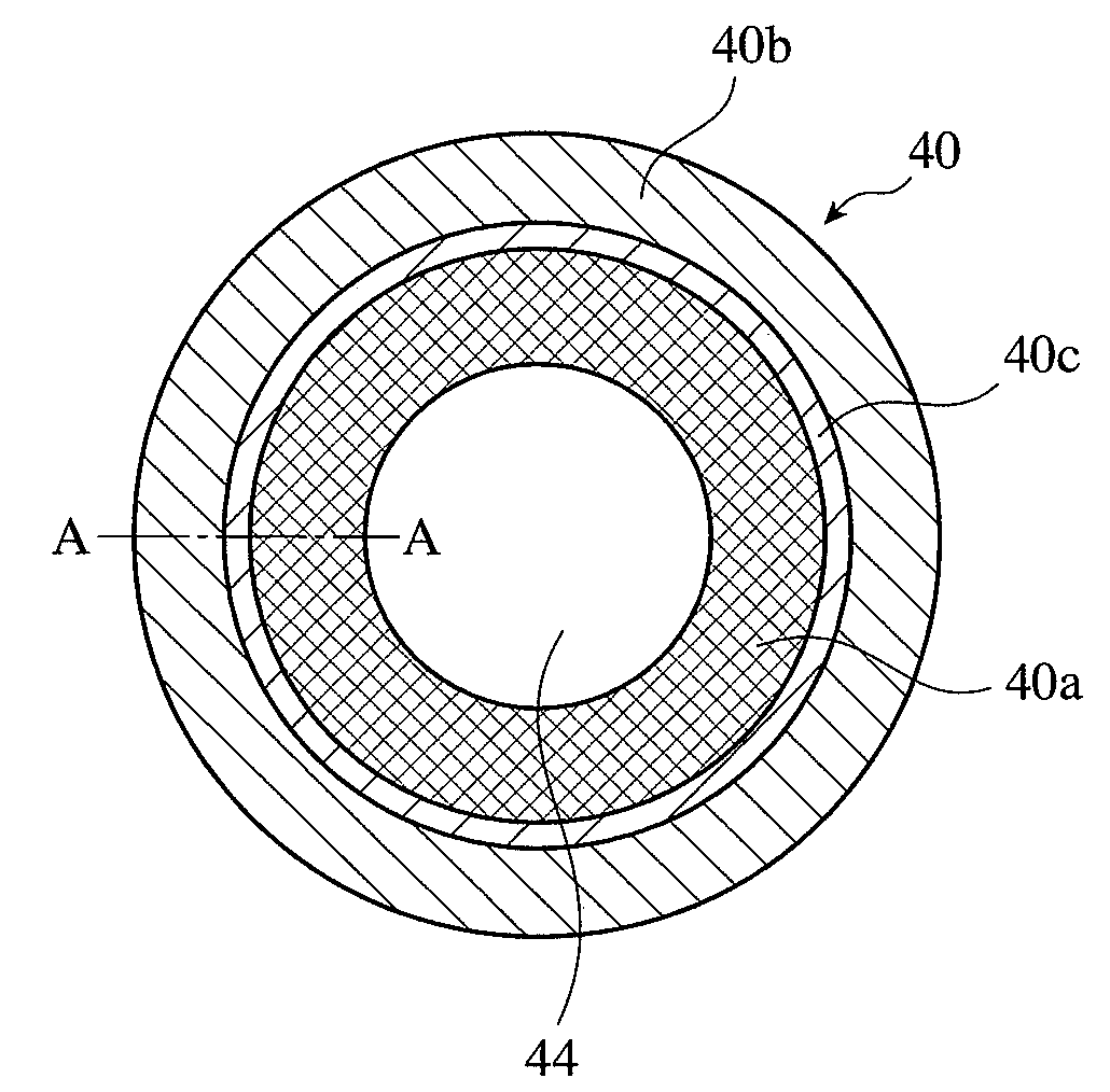
[0200]After the outer layer melt of Reference Example 1 shown in Table 1 was centrifugally cast using a mold having an inner diameter of 450 mm and a length of 800 mm, the intermediate layer melt of Reference Example 6 shown in Table 4 was charged into the resultant outer layer. The resultant cylindrical body comprising an outer layer and an intermediate layer was taken out of the centrifugally casting mold, and a spheroidal graphite cast iron melt comprising by mass 3.3% of C, 1.8% of Si, 0.4% of Mn, 0.4% of Cr, 0.5% of Mo, and 2.2% of Ni, the balance being substantially Fe and inevitable impurities, was charged into the intermediate layer by a stationarily casting method, to form an inner layer, thereby obtaining a composite roll precursor. An MC-carbide-poor portion [an MC-carbide-poor outside layer 40b and a layer 40c having a gradually changing area ratio of MC carbide particles shown in FIGS. 4(b) and 4(c)] was removed from a body surface of this composite roll precursor by ma...


PUM

PropertyMeasurementUnit
equivalent-circle diametersaaaaaaaaaa

Abstract

A centrifugally cast composite roll comprising an outer layer having a composition comprising by mass 2.5-9% of C, 0.1-3.5% of Si, 0.1-3.5% of Mn, and 11-40% of V, the balance being Fe and inevitable impurities; an intermediate layer made of a high-speed steel alloy, which is formed inside the outer layer; and an inner layer made of cast iron or steel, which is formed inside the intermediate layer.

Description

FIELD OF THE INVENTION[0001]The present invention relates to a centrifugally cast composite roll having excellent wear resistance, particularly to a centrifugally cast composite roll suitable for a work roll at a finishing train of a hot strip mill.BACKGROUND OF THE INVENTION[0002]The wear resistance and surface roughening resistance of a roll are important properties determining the productivity of rolling. Poor wear resistance causes a roll surface to be prematurely worn, resulting in rolled products with deteriorated dimensional precision. Also, when a roll surface is unevenly worn and roughened by contact with a work, a back-up roll, etc., such surface roughness is transferred to a work surface, resulting in a work with deteriorated appearance. To prevent these problems, the roll should be exchanged frequently, resulting in frequent stop of a rolling operation and thus decrease in the productivity of rolling factories, cost increase by the grinding of a roll surface, and the red...

Claims


Application Information

Patent Timeline
Patent Type & Authority Applications(United States)
IPC IPC(8): B32B15/18
CPCB21B27/03B22D13/04B32B15/011C22C37/00C22C37/06Y10T428/12965C22C38/22C22C38/24Y10T428/12778Y10T428/12951Y10T428/12979C22C37/10B22D13/00
Inventor FURUSHIMA, KIYOSHIMATSUMOTO, SHUNJIHONDA, RYOTAHAYASHI, KIYOSHIHONDA, TAKASHIUCHIDA, MASATSUGUOYAMA, SEIJIOSUE, TAKUYA
Owner HITACHI METALS LTD
Why Eureka
Try Eureka