
Sprocket opening alignment process and apparatus for multilayer solder decal

a multi-layer solder decal and socket opening technology, applied in non-electric welding apparatus, resistive material coating, solid-state devices, etc., can solve problems such as affecting reliability, new challenges in the area of solder on organic substrates, and difficulty in applying solder paste in sufficient volumes for ever smaller pitches

Inactive Publication Date: 2009-04-09
IBM CORP
View PDF11 Cites 42 Cited by
  • Summary
  • Abstract
  • Description
  • Claims
  • Application Information

AI Technical Summary

Benefits of technology

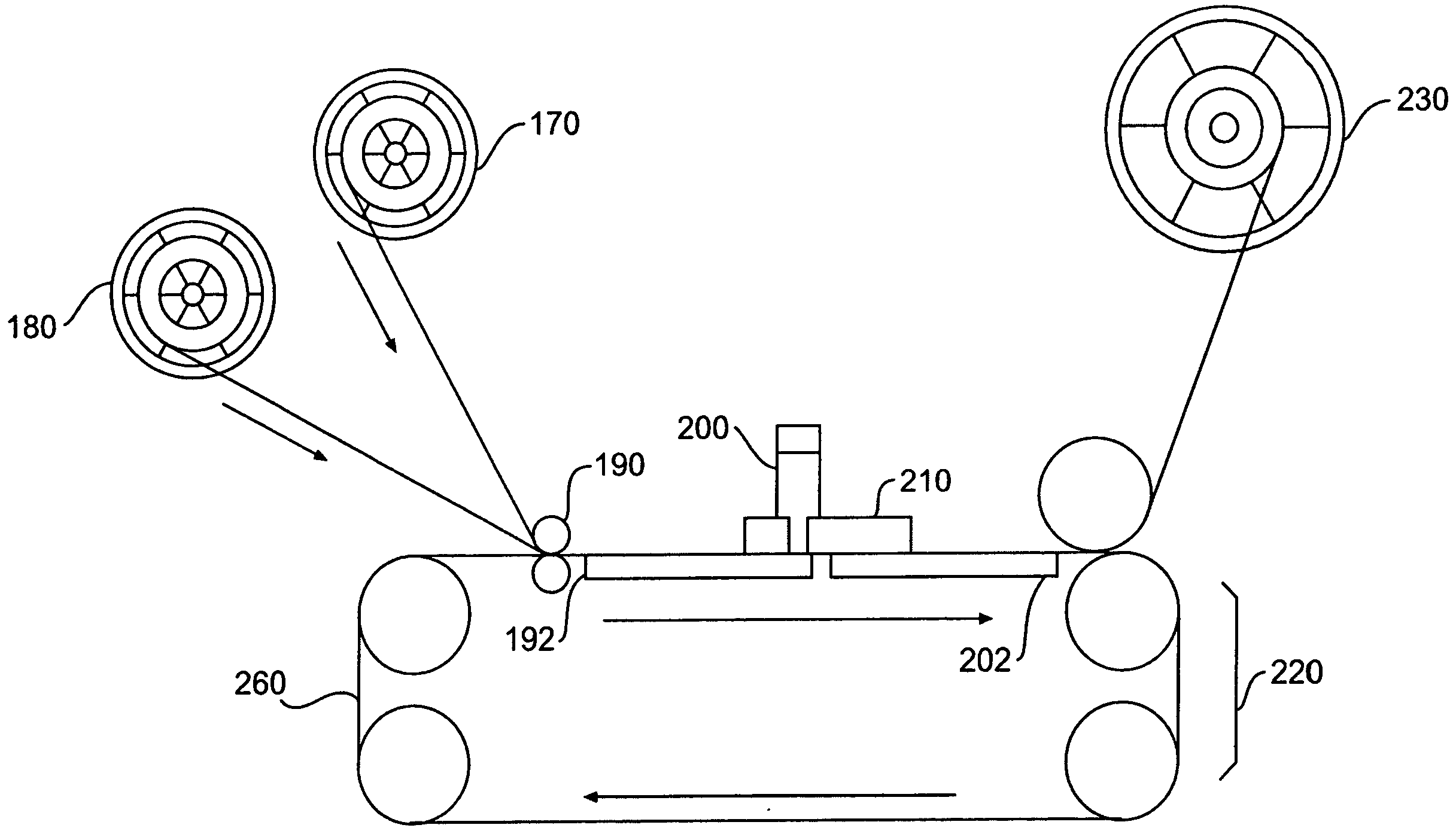
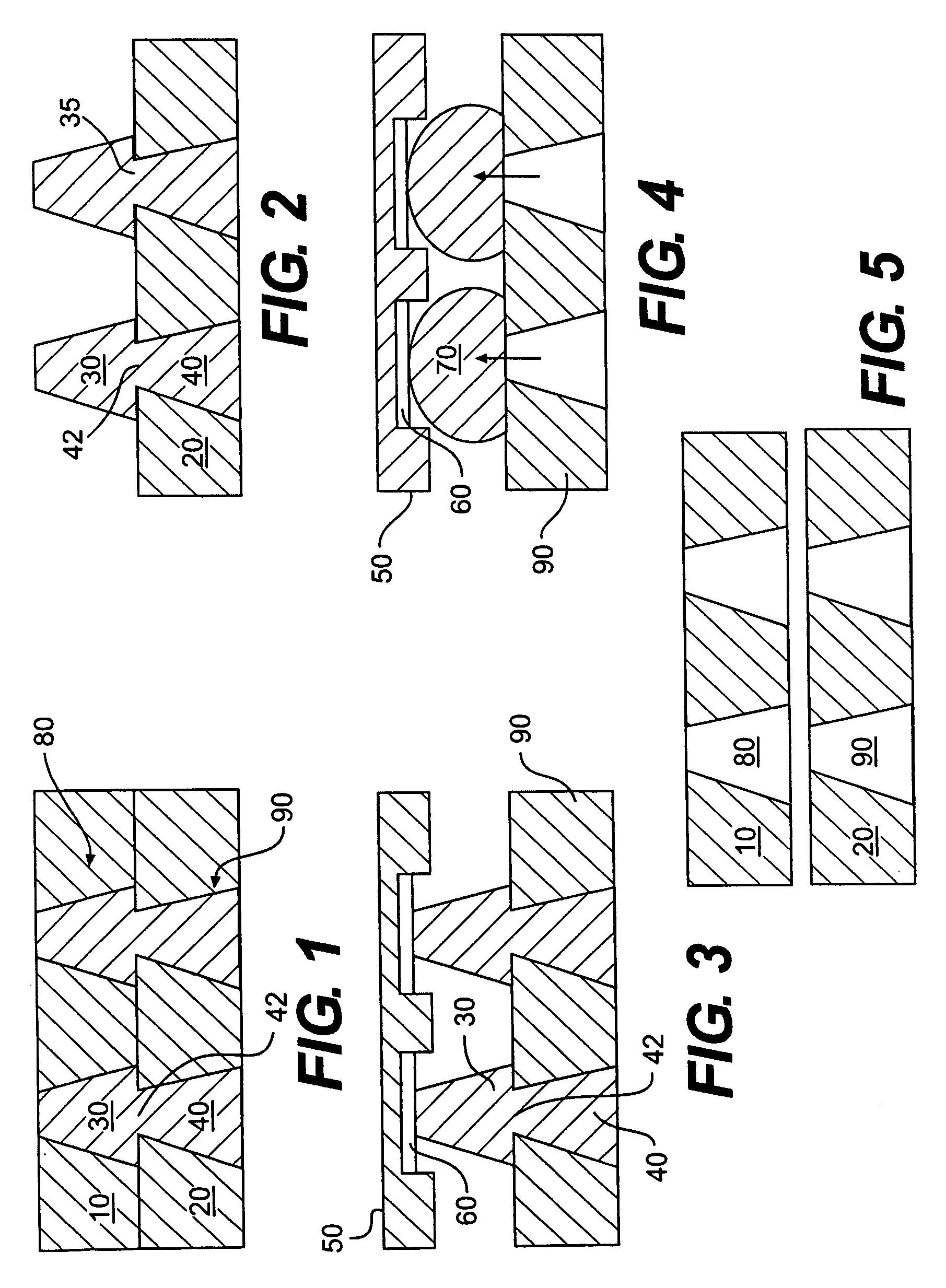
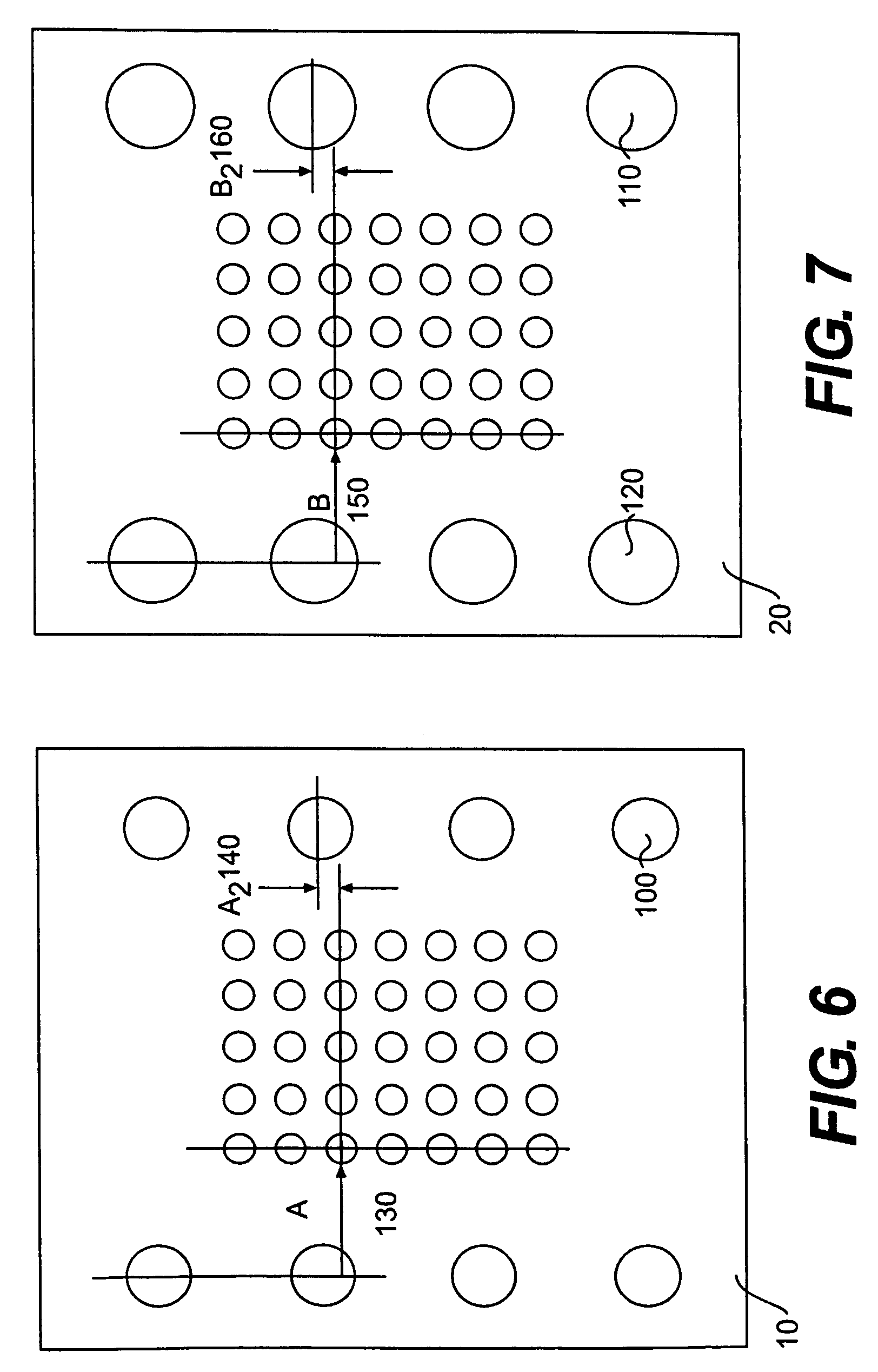
The present invention provides a process and apparatus for obtaining a device comprising soldered electronic components, especially IC devices soldered to electrically conductive substrates, by using IMS processes and minimizing or eliminating difficulties encountered in related art processes. The invention also includes a product produced by the process. The invention addresses the need for a more efficient and repeatable alignment method for manufacturing electronic devices on a large scale. The invention uses a new method and apparatus to align reservoir openings in solder decal layers by positioning the reservoir openings in at least two layers and using a sprocket with diminishing diameters to effect substantial alignment of the center axes of the reservoir openings and the center axes of the sprocket openings.

Problems solved by technology

Solder pastes consist of a mixture of solder metal and flux utilized in a reflow process that results in the formation of voids in the solder joint that in some applications can affect reliability.
As IBM's new interconnect technology, C4NP, however, continues to gain visibility and attention in the industry, new challenges arise in the area of solder on organic substrates.
Inherent volume reductions of between 30-50% between the paste as applied and the final solder volume after reflow make it difficult to apply solder paste in sufficient volumes for ever smaller pitches.
Consequently, at the tightest pitches, the screen openings for the solder paste application begin to overlap, thus fundamentally limiting the technology.
No easy solutions exist for these limitations.
For jetting, however, the technology does not readily lend itself to mass production, but is more suited for prototyping.
For ball drop, the expense of the preformed solder balls becomes ever higher with smaller sizes, and also presents difficulties of grappling with the methods of applying thousands of such balls quickly, efficiently, and on a large scale.
Thus, both of these alternative solutions are not workable in manufacturing that requires precision, relatively high speed, and low cost processes.
Gruber, U.S. Pat. Nos. 5,673,846 and 6,294,745 describes a solder decal apparatus and process to provide a solution to these challenges, and while both disclose the advantages of external solder features to assure reliable transfer, as well as dual layer decals to achieve this, they do not disclose a robust method to provide alignment between the decal layers for efficient manufacture on a large scale.
Misalignment reduces or prevents complete or substantially complete transfer of the solder, which in turn can have an adverse affect on the device or in the manufacturing process of the device.

Method used


Image

  • Sprocket opening alignment process and apparatus for multilayer solder decal
  • Sprocket opening alignment process and apparatus for multilayer solder decal
  • Sprocket opening alignment process and apparatus for multilayer solder decal

Examples


Embodiment Construction

[0025]We disclose the following detailed embodiments of the present invention as examples of the invention which can be embodied in various forms. These specific structural and functional details comprise a basis for the claims and a basis for teaching one skilled in the art to employ the present invention in any appropriately detailed process or structure. We also employ the terms and phrases of this disclosure to provide an understandable description of the invention.

[0026]To achieve these and other advantages, and in accordance with the purpose as embodied and broadly described herein we provide a process and apparatus for aligning a plurality of layers comprising at least two layers that can be positioned in an abutting relationship with each other comprising forming a plurality of sprocket openings in each of the layers for receiving a sprocket of diminishing diameters as the sprocket extends outwardly from a base, with the center axes of the sprocket openings in each layer bei...


PUM

PropertyMeasurementUnit
diametersaaaaaaaaaa
diameteraaaaaaaaaa
areaaaaaaaaaaa

Abstract

A process for aligning at least two layers in an abutting relationship with each other comprises forming a plurality of sprocket openings in each of the layers for receiving a sprocket of diminishing diameters as the sprocket extends outwardly from a base, with the center axes of the sprocket openings in each layer being substantially alignable with one another, the diameter of the sprocket openings in an abutting layer for first receiving the sprocket being greater than the diameter of the sprocket openings in an abutted layer. This is followed by forming a plurality of reservoir openings in each of at least two of the layers and positioning the sprocket openings in the layers to correspond with one another and the reservoir openings in the layers to correspond with one another so that substantial alignment of the center axes of the corresponding sprocket openings in the layers effects substantial alignment of the center axes of the corresponding reservoir openings in the layers. Engaging the sprocket openings with the sprocket by inserting the end of the sprocket having the smallest diameter into the sprocket openings having the largest diameter in the layers and continuing through to the sprocket opening having the smallest diameter in the layers effects substantial alignment of the center axes of the corresponding sprocket openings and substantial alignment of the center axes of the corresponding reservoir openings in the layers. The invention also comprises apparatus-for performing this process.

Description

FIELD OF THE INVENTION[0001]The present invention generally relates to the field of injection molding of solder (IMS), and more particularly relates to the making of multilayer solder decals.RELATED ART[0002]Gruber et al. in their paper “Low-cost wafer bumping,”IBM Journal of Research and Development, IBM JRD 49-4 / 5 (http: / / www.research.ibm.com / jpourna / rd / 494 / gruber.html) (Aug. 16, 2005) describe flip-chip solder-bump interconnections as the face-down soldering of integrated circuit (IC) devices to chip carriers by means of conductive bumps on the chip bond pad. The use of this bump technology also extends to passive filters, detector arrays and MEMs devices. IBM introduced this technology in the early 1960's with the solid logic technology in the IBM System / 360™. It extended interconnection capabilities beyond existing wire-bonding techniques, allowing the area array solder-bump configuration to extend over the entire surface of the chip (die) providing solder bumps for interconnec...

Claims


Application Information

Patent Timeline
Patent Type & Authority Applications(United States)
IPC IPC(8): H01L21/44B23K1/00
CPCH01L2924/14H01L24/13Y10T29/49149H01L2224/11849H01L2224/1131H01L2924/0002H01L2224/1111H01L24/11H01L2224/131H01L24/742H01L2224/0401H01L2224/05571H01L2224/11003H01L2924/00012H01L2924/014H01L2224/05552
Inventor BUCHWALTER, STEPHEN L.GRUBER, PETER A.NAH, JAE-WOONGSHIH, DA-YUAN
Owner IBM CORP
Learn More