Methods and apparatus for reducing radiated field feedback in radio frequency transmitters

a radio frequency transmitter and radiated field technology, applied in the field of wireless communication, can solve the problems of unstable or inoperable vco 110, more prone to process-related failures, unstable or inoperable vco, etc., and achieve the effect of reducing radiated field feedback and substantially avoiding radiated field feedback from pa to lfo

Inactive Publication Date: 2009-04-09
PANASONIC CORP
View PDF10 Cites 13 Cited by
  • Summary
  • Abstract
  • Description
  • Claims
  • Application Information

AI Technical Summary

Benefits of technology

[0008]Methods and apparatus for reducing radiated field feedback in radio frequency (RF) transmitters are disclosed. An exemplary radio transmitter includes a baseband processor, an upconverter, and an RF module containing both a power amplifier (PA) and a co-located low-field oscillator (LFO). By using an LFO for the transmitter's local oscillator, rather than a conventional voltage controlled oscillator (VCO) constructed from coils or spiraled inductors, radiated field feedback from the PA to the LFO is substantially avoided.
[0009]According to another aspect of the invention, in addition to, or instead of using an LFO to reduce radiated field feedback, an LFO or VCO of a radio transmitter is configured to operate at a harmonic of the system output signal frequency, i.e., at a harmonic of the frequency of the RF signal generated and radiated by the radio system's PA and antenna. A frequency divider circuit is included to divide the frequency of the signal from the LFO or VCO down to the desired output signal frequency. Operating the LFO or VCO at a harmonic reduces the degree by which electromagnetic fields generated by the PA and antenna interfere with electromagnetic fields generated by the LFO or VCO. In other words, radiated field feedback between the PA and the LFO or VCO is substantially avoided by operating the LFO or VCO at a harmonic of the system output frequency. Radiated field feedback can also be reduced by configuring the LFO or VCO to operate at a frequency that is a non-integer multiple of the fundamental frequency (i.e., not at a harmonic of the fundamental frequency), and using a fractional (i.e., non-integer) frequency divider circuit to divide the frequency of the signal down to the desired PA output signal frequency.
[0010]Using an LFO and / or operating the LFO or VCO at a different frequency than the PA output frequency provides a number of advantages over prior art approaches. Higher levels of integration can be achieved since the oscillator circuitry, which has been traditionally formed on a separate mixed-signal RFIC, can be formed on the same module or integrated circuit chip as the radio system's PA. By moving digital circuitry traditionally formed on the separate mixed-signal RFIC to the all-digital baseband integrated circuit, the need for a separate and dedicated RFIC can be eliminated and, as a consequence, the overall chip count needed to implement the radio system is reduced. Moreover, production costs relating to poor yields caused by the co-integration of analog oscillator circuitry (such as the oscillator circuitry) with digital circuitry on a separate mixed-signal RFIC are reduced.

Problems solved by technology

As explained below, these efforts are presented with various challenges and obstacles relating to the co-location or co-integration of certain radio system elements.
This “radiated field feedback” phenomenon, which is conceptually illustrated in FIG. 2, is highly undesirable since it adversely affects the intended operating frequency of the VCO 110, contributes to signal distortion at the output of the PA 114, and can even render the VCO 110 unstable or inoperable.
Unfortunately, integrating the VCO 110 on the RFIC 106 seriously comprises the manufacturing yields of the RFIC 106.
In general, mixing analog and digital circuitry on the same IC results in low production yields.
Analog circuitry is much more sensitive to processing variations than is digital circuitry and, therefore, is more prone to process-related failures.
This large area of occupation increases the probability of yield losses.
Unfortunately, the buffer zones substantially reduce the available chip area for other electrical components on the RFIC 106.

Method used


Image

  • Methods and apparatus for reducing radiated field feedback in radio frequency transmitters
  • Methods and apparatus for reducing radiated field feedback in radio frequency transmitters
  • Methods and apparatus for reducing radiated field feedback in radio frequency transmitters

Examples


Embodiment Construction

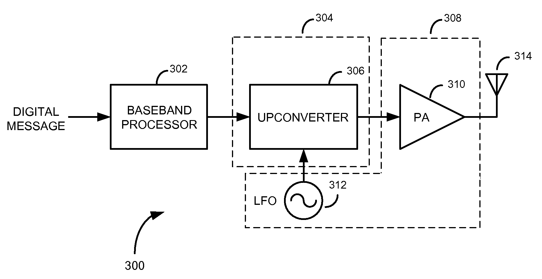
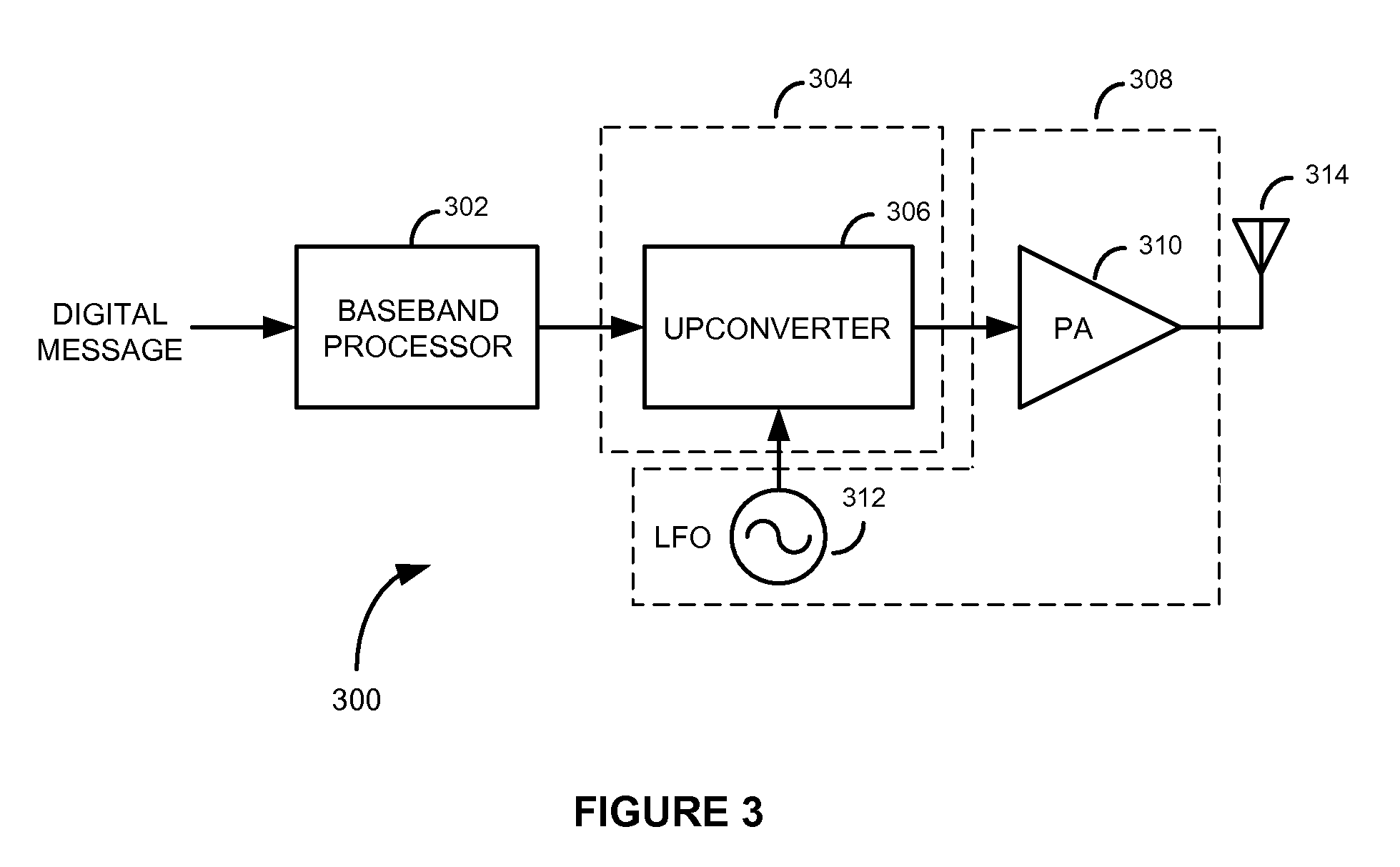
[0024]FIG. 3 is a block diagram of a radio frequency (RF) transmitter 300, according to an embodiment of the present invention. The RF transmitter 300 comprises a baseband processor 302, an RF integrated circuit (RFIC) 304 having an upconverter 306, a power amplifier (PA) module 308 having a PA 310 that is co-located with a low-field oscillator (LFO) 312, and an antenna 314. The baseband processor 302 is configured to receive a digital message and modulate the digital message according to any one of a number of baseband modulation schemes (e.g., Gaussian Minimum Shift Keying (GMSK), quadrature or 3π / 8 8-phase shift keying (8-PSK), or some other modulation scheme), thereby generating digital baseband signals. A digital-to-analog converter (DAC), which may be configured within either the baseband processor 302 or the RFIC 304, converts the baseband signals to analog signals. These analog signals are then upconverted to RF by the upconverter 306, according to a carrier frequency provid...


PUM


Abstract

Methods and apparatus for reducing radiated field feedback in radio frequency (RF) transmitters. An exemplary RF transmitter includes a power amplifier (PA) and a low-field oscillator (LFO) that are co-located, either on a common module or integrated in the same integrated circuit chip. By using an LFO for the transmitter's local oscillator, radiated field feedback from the PA to the LFO is substantially reduced. In addition to, or instead of using an LFO to reduce radiated field feedback, the LFO or a voltage controlled oscillator (VCO) may be configured to operate at either a harmonic or a non-integer multiple of the transmitter's output signal frequency. Using an LFO or VCO and / or operating the oscillator at a harmonic or a non-integer multiple of the radio system output signal frequency reduces the degree by which electromagnetic fields generated by the radio system's PA and antenna interfere with electromagnetic fields generated by the LFO or VCO, thereby allowing the LFO or VCO to be co-located with or integrated in the same integrated circuit chip as the radio system's PA.

Description

FIELD OF THE INVENTION[0001]The present invention relates to wireless communications. More specifically, the present invention relates to methods and apparatus for reducing radiated field feedback in radio frequency (RF) transmitters.BACKGROUND OF THE INVENTION[0002]To satisfy consumer demand for smaller and more power-efficient wireless communications devices, radio engineers continue to seek new ways of miniaturizing the radio systems used in such devices. The availability of integrated circuit technology has contributed significantly to this miniaturization effort. For example, most all electrical components of state-of-the art radio systems used in cellular communications applications can now be implemented on only a few integrated circuit chips. These integrated solutions allow the manufacture of small, lightweight and power-efficient wireless communications devices. Even with these advances, radio engineers continue to seek new ways of reducing the size of radio systems even f...

Claims


Application Information

Patent Timeline
Patent Type & Authority Applications(United States)
IPC IPC(8): H04B1/04
CPCH04B1/04
Inventor MCCUNE, JR., EARL W.
Owner PANASONIC CORP
Why Eureka
Try Eureka