Circuit board and method of producing the same

a technology of circuit board and core section, applied in the direction of conductive pattern formation, conductive substrate adhesion improvement, printed circuit aspects, etc., can solve the problems of heat stress between the core section and the cable layer, electrical shortening of the core section, and difficult to perfectly coat the rough inner face of the pilot hol

Inactive Publication Date: 2009-04-16
FUJITSU LTD
View PDF7 Cites 16 Cited by
  • Summary
  • Abstract
  • Description
  • Claims
  • Application Information

AI Technical Summary

Benefits of technology

[0008]An object of the present invention is to provide a highly reliable circuit board, which is capable of tightly bonding a cable layer on a base member even if thermal expansion coefficients of the two are significantly different.
[0015]In the circuit board, an inner face of the pilot hole may be coated with a plated layer; and the pilot hole may be filled with an insulating material, thereby short circuit between the conductive core section and the plated through-hole section can be prevented. Further, the inner face of the pilot hole may be further coated with an insulating film formed on the plated layer, thereby the short circuit between the conductive core section and the plated through-hole section can be securely prevented.
[0017]In the method, the cable layer may be integrated with the base member, in said laminating step, by heating and pressurizing a cable sheet on the base member together with a prepreg, thereby the cable layer can be easily integrally laminated on the base member.
[0020]In the method, the base member may have an electrically conductive core section; a pilot hole for forming a plated through-hole section may be formed in the core section; and the base member, in which the pilot hole has been formed, may be plated so as to coat an inner face of the pilot hole with a plated layer and coat the surface of the base member with the conductive layer, thereby the short circuit between the conductive core section and the plated through-hole section can be securely prevented.
[0021]In the method, the inner face of the pilot hole, which has been coated with the plated layer, may be further coated with an insulating film by an electrodeposition method, in which the plated layer is used as an electric power feeding layer, thereby the short circuit between the conductive core section and the plated through-hole section can be further securely prevented.
[0025]In the circuit board and the method of the present invention, the anchor patterns are formed on the surface of the base member, and then the cable layer is laminated on the anchor patterns, so that the cable layer can be tightly bonded on the base member by anchoring functions of the anchor patterns. Therefore, even if thermal expansion coefficients of the base member and the cable layer are significantly different, separating the cable layer from the base member and forming a crack therebetween can be prevented.

Problems solved by technology

However, if the pilot holes are drilled, burrs are formed on inner faces of the pilot holes and the plated through-hole sections and the core section will be electrically shorted.
However, it is difficult to perfectly coat the rough inner faces of the pilot holes.
The problem of the heat stresses between the core section and the cable layers will occur in not only substrates having electrically conductive core sections but also generic substrates.

Method used


Image

  • Circuit board and method of producing the same
  • Circuit board and method of producing the same
  • Circuit board and method of producing the same

Examples


Embodiment Construction

[0037]Preferred embodiments of the present invention will now be described in detail with reference to the accompanying drawings.

(Steps of Forming Core Substrate)

[0038]In the following description, a method of producing a core substrate, which has an electrically conductive core section, will be explained as embodiments of the present invention.

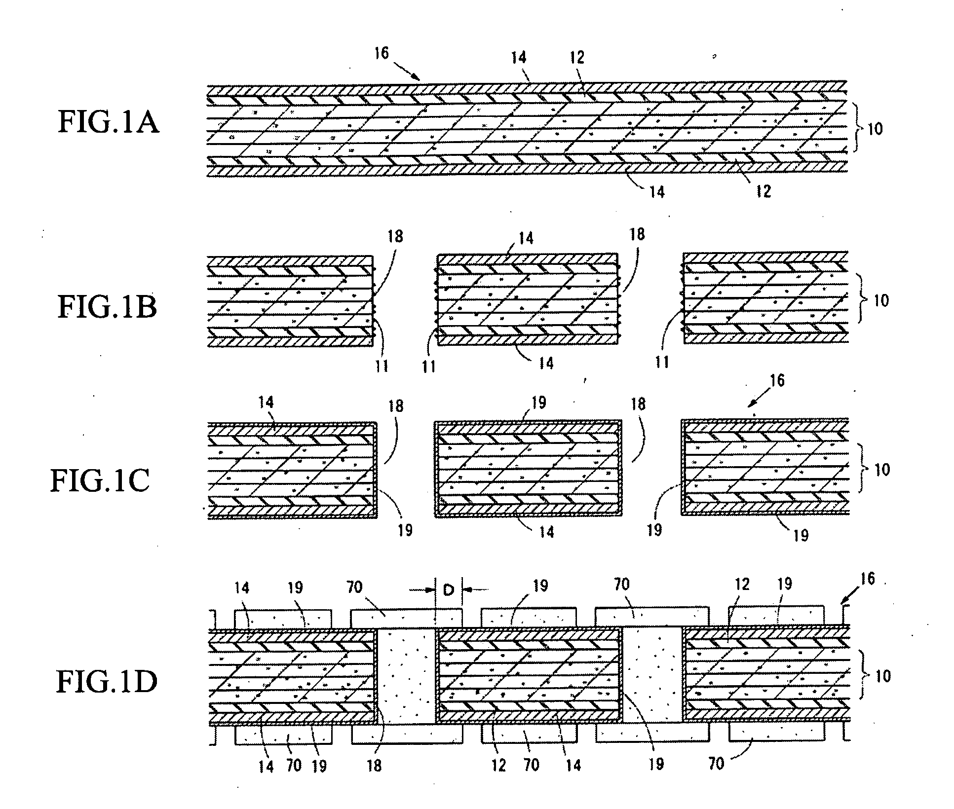
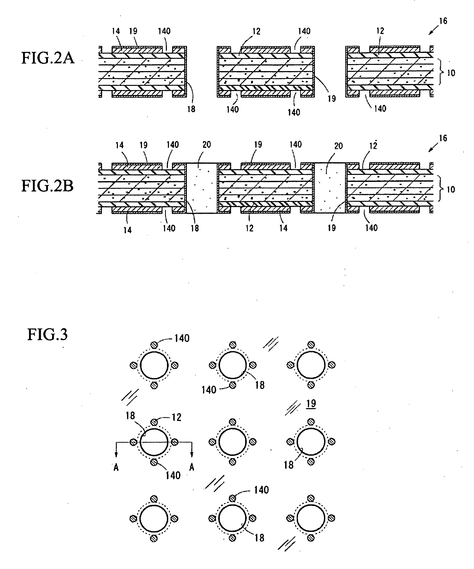
[0039]FIGS. 1A-2B show the steps of: forming pilot holes, through which plated through-hole sections will be respectively pierced, in a base member; forming gas purging holes; and filling the pilot holes with insulating materials.

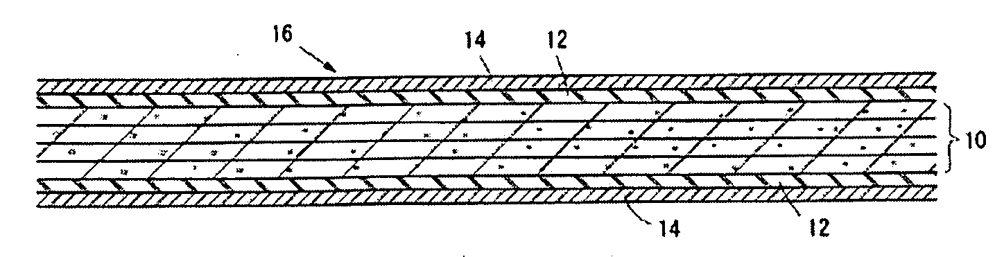
[0040]FIG. 1A shows a flat plate-shaped base member 16, which comprises a core section 10 composed of carbon fiber-reinforced plastic and copper foils 14 respectively bonded on the both side faces of the core section 10 with prepregs 12. The core section 10 is formed by the steps of: laminating four prepregs, each of which is formed by impregnating a carbon cloth with polymer, e.g., epoxy resin; and heating and press...


PUM

PropertyMeasurementUnit
diametersaaaaaaaaaa
diametersaaaaaaaaaa
thicknessaaaaaaaaaa

Abstract

The circuit board is capable of tightly bonding a cable layer on a base member even if thermal expansion coefficients of the base member and the cable layer are significantly different. The circuit board comprises: the base member; and the cable layer being laminated on the base member with anchor patterns, which are electrically conductive layers formed on a surface of the base member.

Description

BACKGROUND OF THE INVENTION[0001]The present invention relates to a circuit board and a method of producing the circuit board, more precisely relates to a circuit board, in which a base member and a cable layer have different thermal expansion coefficients, and a method of producing the circuit board.[0002]Some test substrates, which are used for testing circuit boards, on which semiconductor elements will be mounted, and semiconductor wafers, include core substrates composed of carbon fiber-reinforced plastic (CFRP). In comparison with conventional glass-epoxy core substrates, thermal expansion coefficients of the core substrates composed of carbon fiber-reinforced plastic are small, and thermal expansion coefficients of the circuit boards having such core substrates can be corresponded to those of semiconductor elements to be mounted on the circuit boards. Therefore, thermal stress generated between a semiconductor element and a circuit board can be effectively avoided.[0003]The c...

Claims


Application Information

Patent Timeline
Patent Type & Authority Applications(United States)
IPC IPC(8): H05K1/02H05K3/10
CPCH05K3/38H05K3/429H05K3/4608H05K3/4611H05K3/4691H05K9/00Y10T29/49155H05K2201/0323H05K2201/09581H05K2201/0959H05K2201/09781H05K2201/09809H05K2201/2072H05K2201/0281H05K1/02
Inventor IIDA, KENJIABE, TOMOYUKIMAEHARA, YASUTOMOHIRANO, SHINNAKAGAWA, TAKASHIYOSHIMURA, HIDEAKIYAMAWAKI, SEIGOOZAKI, NORIKAZU
Owner FUJITSU LTD
Why Eureka
Try Eureka