X-ray line array detector

a line array detector and detector technology, applied in the field of x-ray line array detectors, can solve the problems of etch damage to the integrated circuit, photosensors and the integrated circuits behind them, and achieve the effects of prolonging the lifetime of the line array detector, avoiding damage, and greatly enhancing the anti-radiation performance of the detector

Inactive Publication Date: 2009-04-16
YU HONGLIN +4
View PDF3 Cites 13 Cited by
  • Summary
  • Abstract
  • Description
  • Claims
  • Application Information

AI Technical Summary

Benefits of technology

[0016]According to the invention, the bundle of light-guide fibers is provided between the emergent surface of the flicker body and the incident surface of the array of photosensors, and the bundle of light-guide fibers has at least one bend or the incident direction and the emergent direction are not in a same line, so that X-rays transmitting through the flicker body can not irradiate the photosensors and integrated circuits behind them, thereby avoiding damage resulting from long-term use

Problems solved by technology

In an existing line array detector, due to the compact integral incorporation of the flicker body 102, the array of photosensors 103, and the shift amplifier 104, such a structure has a significant drawback in that X-rays transmitting through the flicker body directly irr

Method used


Image

  • X-ray line array detector
  • X-ray line array detector
  • X-ray line array detector

Examples


first embodiment

The First Embodiment

[0023]This embodiment is consisted of an X-ray probe, a signal acquisition circuit, and a low voltage power source combination.

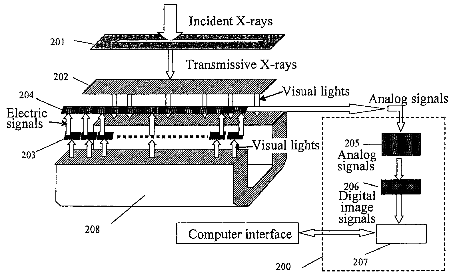
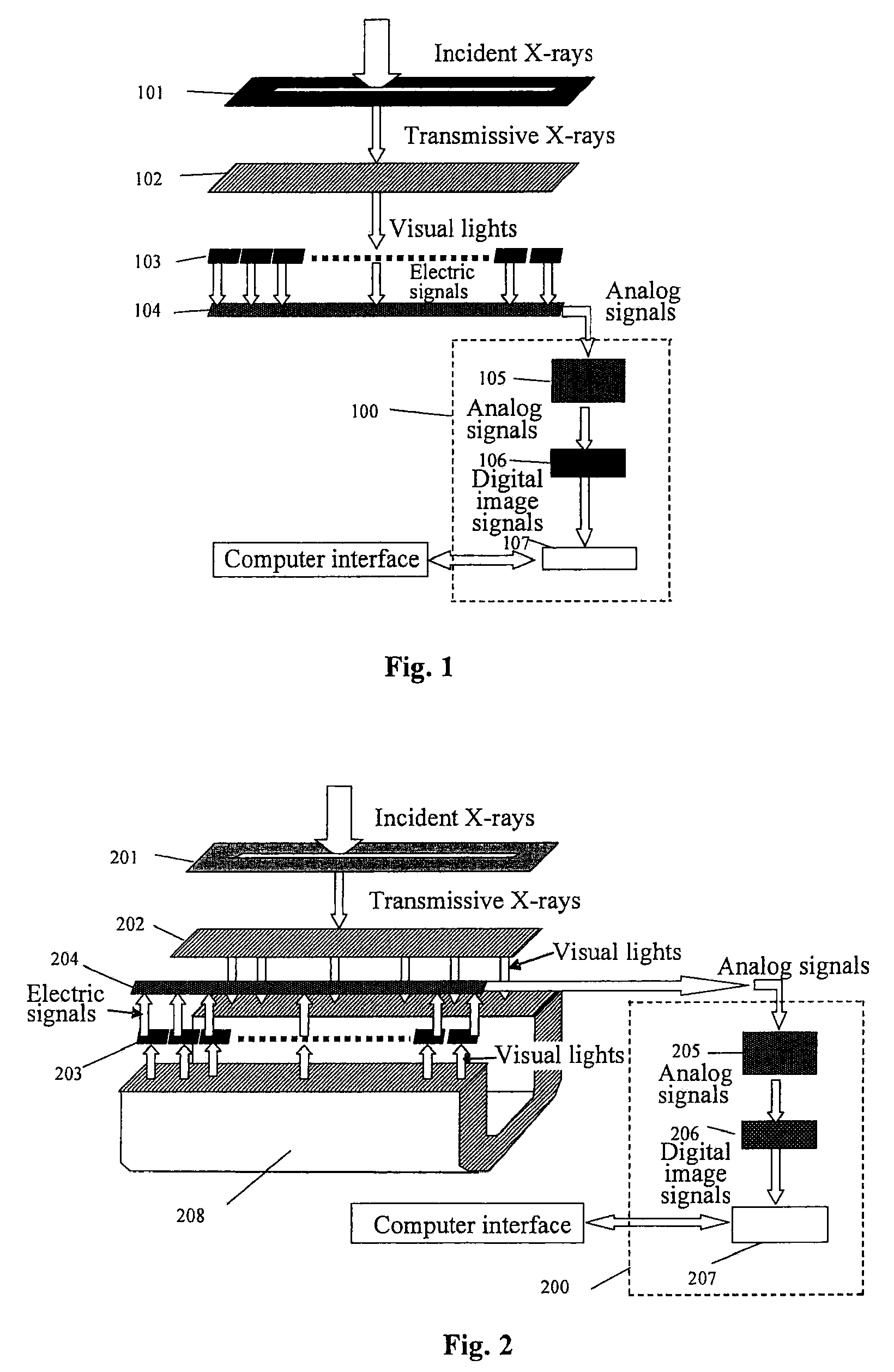
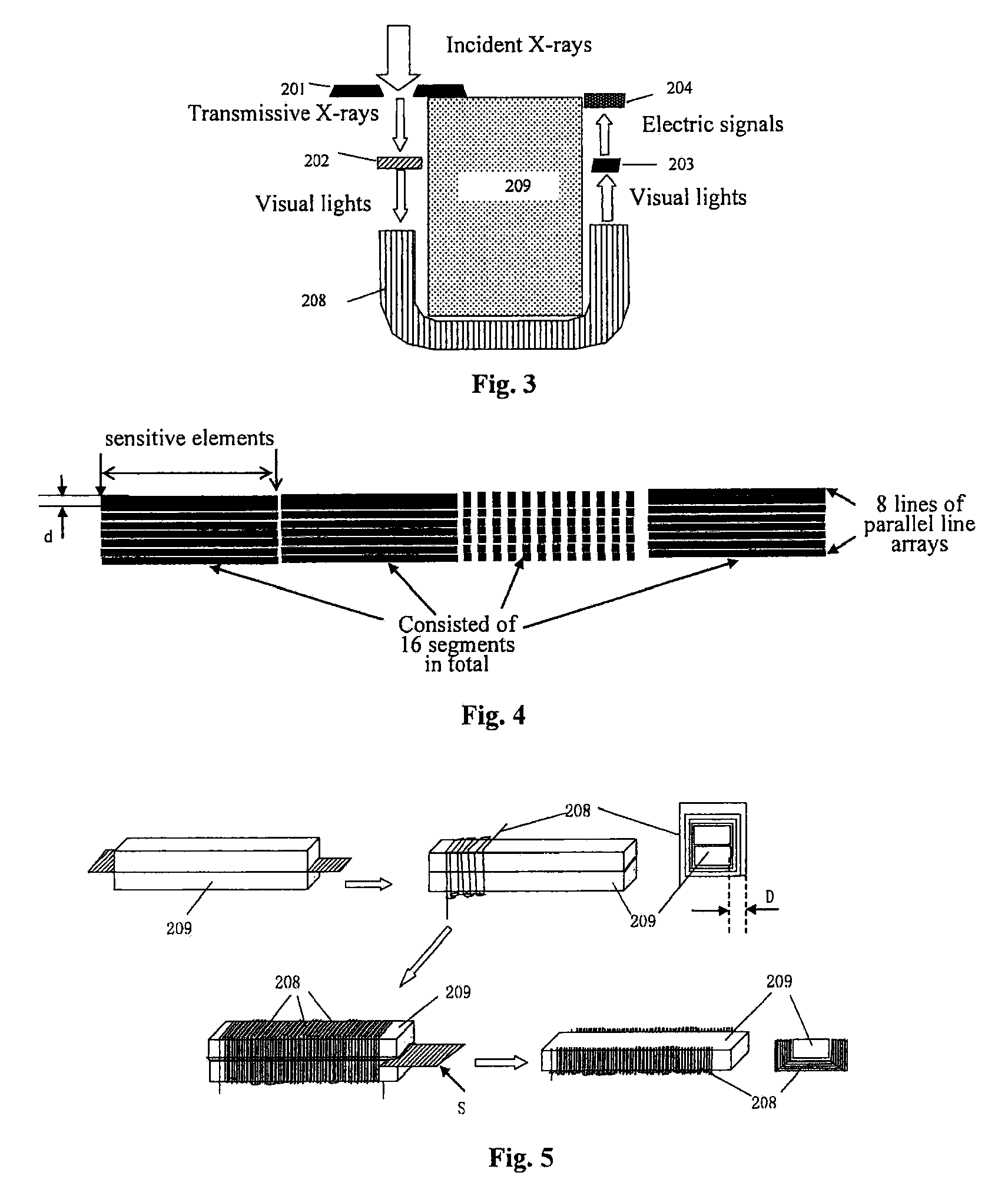
[0024]As illustrated in FIG. 2 and FIG. 3, the X-ray probe is a closed aluminum alloy chamber including a collimator 201, a flicker body 202, an array of photosensors 203, and a shift amplifier 204. A front panel is made of a lead antimony alloy material with shielding functions, and at its upper part, there is provided the bar collimator 201 of a 410 mm length and a 1.6 mm width. The top of the collimator is sealed with an aluminum film to serve as an incident window for X-rays, and the flicker body 202 is provided below the collimator and converts incident X-rays energy into light energy with a wavelength of 200˜1000 μm. An U-shaped bundle of light-guide fibers 208 is provided between an emergent surface of the flicker body 202 and an incident surface of the array of photosensors 203, so that X-rays transmitting through the flicker body...

second embodiment

The Second Embodiment

[0033]This embodiment as illustrated in FIG. 6 is structured substantially the same as the first embodiment except that the incident surface of the bundle of light-guide fibers 308 is a bevel, X-rays pass through the collimator 301 and then are converted into visual lights through the flicker body 302, and the visual lights irradiate the array of photosensors 303 at the emergent surface after passing the inclined incident surface of the bundle of light-guide fibers 308 and are converted into electric signals in proportion. Thus, X-rays transmitting through the flicker body 302 can not irradiate the photosensors and their integrated circuits, and the photosensors are perfectly protected and the lifetime prolonged. The incident and emergent surfaces of the bundle of light-guide fibers 308 are also bonded respectively with the emergent surface of the flicker body 302 and the incident surface of the array of photosensors 303 with a coupling agent. A shielding body 3...


PUM


Abstract

The present invention relates to an X-ray line array detector in which a bundle of light-guide fibers is provided between an emergent surface of a flicker body and an incident surface of an array of photosensors, and the bundle of light-guide fibers has at least one bend, or an incident direction and an emergent direction are not in a same line, so that X-rays transmitting through the flicker body can not irradiate photosensors and integrated circuits behind them, and that damage resulting from long-term use or a large dose of X-ray radiation can be avoided, thereby prolonging lifetime of the line array detector. Further, a shielding body provided between the emergent surface of the flicker body and the incident surface of the array of photosensors can further shield the photosensors and their integrated circuits from interference of X-rays, so that good protection of the photosensors and their integrated circuits is achieved, thereby enhancing greatly anti-radiation performance of the detector and doubling the lifetime.

Description

FIELD OF THE INVENTION[0001]The present invention relates to an X-ray line array detector.BACKGROUND OF THE INVENTION[0002]The principle for a line array detector to line scan and acquire an image is that an X-ray source is driven by a mechanical scanning device to move in phase with the detector to perform X-ray scan on a person or object to be detected. Each time the mechanical scanning device moves by a unit distance (e.g., 0.2 mm), the detector acquires a line of X-ray image data. If the mechanical scanning device moves by a distance of 40 cm successively and uniformly, the detector acquires 2000 lines of X-ray image data accordingly. The data are processed by a computer to form a frame of an X-ray image of approximately 40 cm×40 cm for the object which is mechanically scanned.[0003]An existing line array detector is structured as illustrated in FIG. 1, and comprises an X-ray probe, a signal acquisition circuit, and a low voltage power source combination. Wherein, the X-ray prob...

Claims


Application Information

Patent Timeline
IPC IPC(8): G01T1/24G02B6/04
CPCG01T1/20
Inventor YU, HONGLINJIN, ZHENGYULI, KUNCHENGSUN, XIAOWEIJIANG, GENDI
Owner YU HONGLIN
Why Eureka
Try Eureka