Tilting Accessory Hitch With Specific Bearing Design

a technology of specific bearings and accessory hooks, which is applied in the field of tilting accessory hooks, can solve the problems of high operator skill, time-consuming and laborious, and the arrangement of the hooks is difficult and fiddly to use, and achieves the effects of high stress, simplified construction, and high stress

Inactive Publication Date: 2009-04-16
SHARP RODNEY WARWICH
View PDF5 Cites 13 Cited by
  • Summary
  • Abstract
  • Description
  • Claims
  • Application Information

AI Technical Summary

Benefits of technology

[0032]According to another aspect of the present invention there is provided a hitch assembly, substantially as described above, which there are provided one or more rings or spacers to help position the rotatable bearing element.
[0097]This arrangement, which may also be implemented on hitch assemblies of standard and known type construction, can significantly reduce the depth (front-to-rear) of hitch assemblies and increase the load manipulating performance of the tractor / accessory combination. The arrangement also allows for the remote release of the accessory if the user so desires—e.g. through control from within the tractor's cab (or elsewhere on the tractor).

Problems solved by technology

A limitation of most tractor and bucket combinations is that the bucket is fixed in rotational orientation about an axis parallel to the longitudinal axis of the tractor.
Accordingly, attempting to level the ground to a particular incline (such as may required in a driveway or courtyard) can be time consuming and greatly dependent on operator skill.
However, the arrangement proved difficult and fiddly to use, requiring the user to manhandle components of the hitch to each new preset.
This was difficult, and made more difficult if foreign material such as clay or soil clogged the system.
While it allowed for rotational bucket inclination, it was not something which could be easily altered (as an operator would want to do).
Secondly, it did not allow infinitely variable adjustment within the limits of permitted inclination, and was limited to inclination in one rotational direction only.
Thirdly, it was heavy and bulky and increased the depth (front-to-back) of the hitch assembly, and weight.
Even standard hitches are of significant depth, and which results in moving the centre of mass of the tractor and load in bucket, forwardly.
This increases the tendency for the tractor to tip forward.
Increased weight also introduces similar problems.
While effective, this design which included a separate attachable rotatable (bearing) assembly, which allowed two frame elements to rotate relative to each other, did suffer from a number of limitations which affected its usefulness and versatility.
For instance, the separate bearing design adopted in the prototypes imposed a number of limitations or disadvantages.
One was that the size of the bearing required in order to achieve sufficient strength and rigidity precluded use with accessories having inner mounted hoses (e.g. Bobcat® brand accessories).
This was a significant limitation, and attempting to address this problem exposed vulnerable hoses to damage.
This results in a number of disadvantages, greatest of which being the fact that the load on the accessory is positioned further forward, upsetting the balance and centre of gravity of the tractor / load combination and possibly requiring counter weighting at the rear of the tractor (reducing the overall performance of the tractor).
From a manufacturing point, the previous design was labour intensive in design, and had several features which localised stress at particular points.

Method used


Image

  • Tilting Accessory Hitch With Specific Bearing Design
  • Tilting Accessory Hitch With Specific Bearing Design
  • Tilting Accessory Hitch With Specific Bearing Design

Examples


example 1

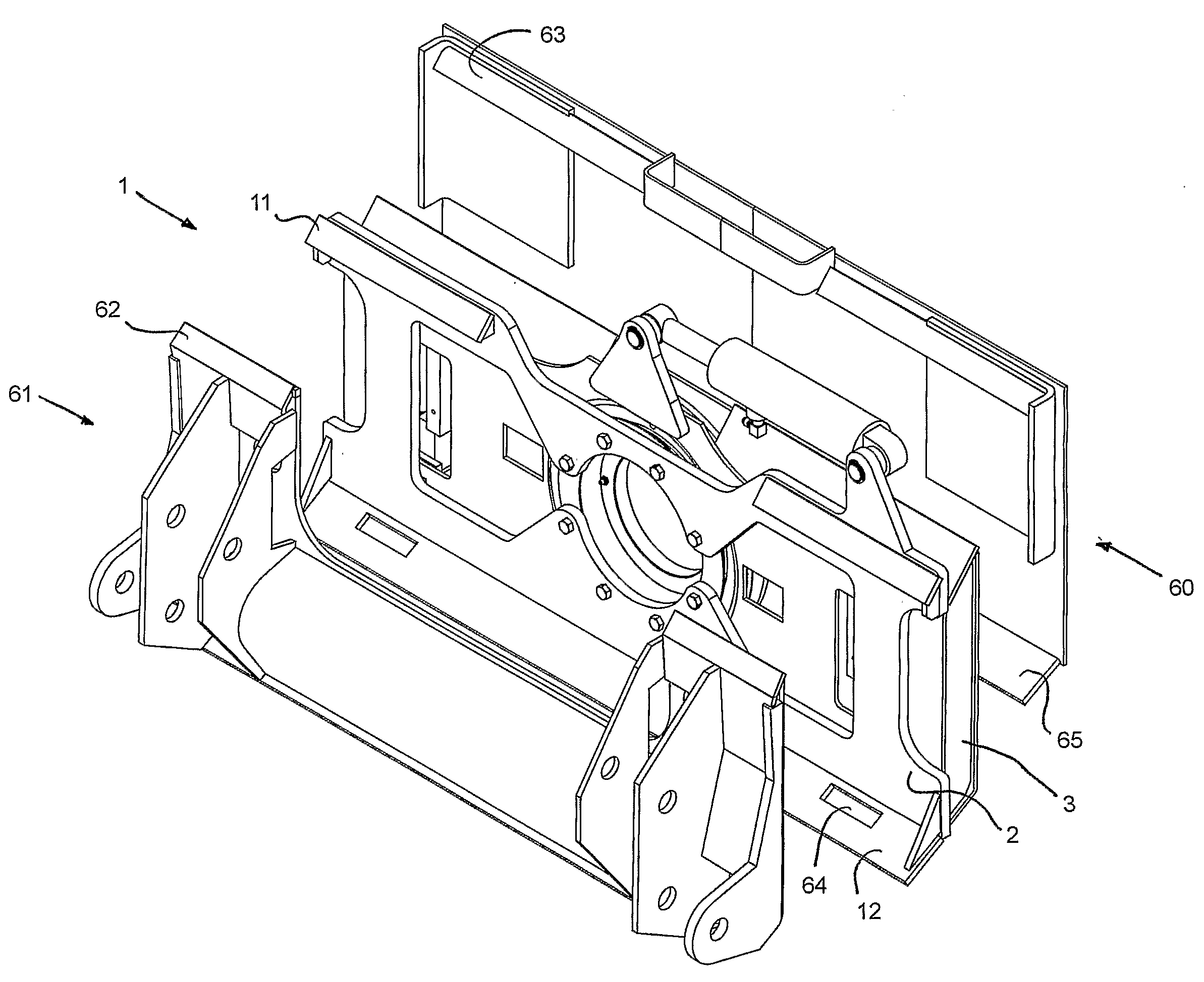
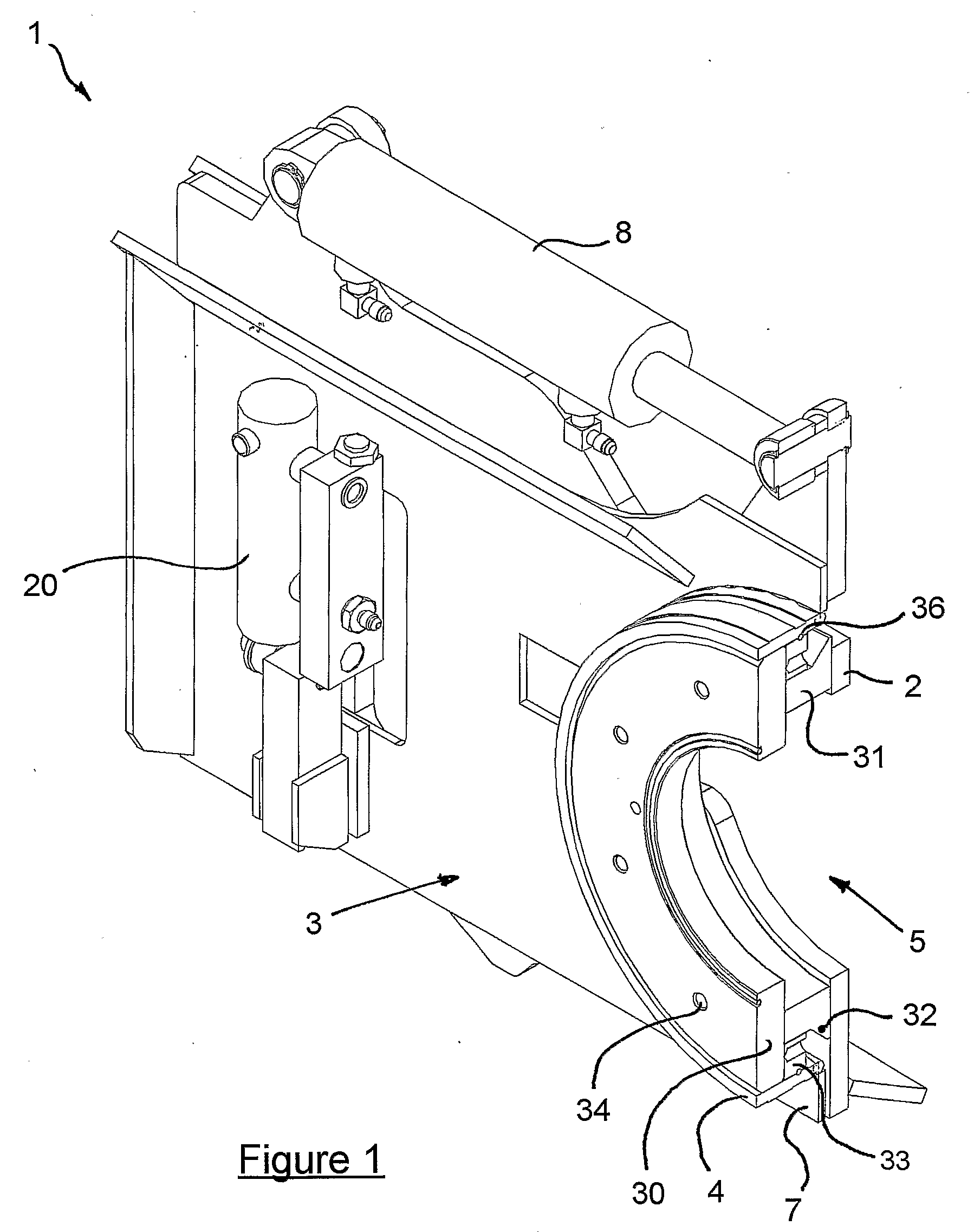
[0108]With reference to the drawings, and by way of example only, there is illustrated an embodiment of the present invention. FIG. 1 provides a cutaway view, which enables various components of the embodiment to be seen.

[0109]Referring to FIG. 1 there is shown a hitch assembly (generally indicated by arrow 1), which comprises a first frame portion (including element 2) attachable to a tractor (not shown) and a second frame portion (generally indicated by arrow 3) to which an accessory (not shown) is attachable. The second frame portion (3) supports an integral bearing support (4) which is annular and continuously welded to back plate (7) of frame portion (3). This acts as a guide for a rotating bearing portion (generally indicated by arrow 5) which is connected to the other frame portion (2). This arrangement allows the frame portions (2, 3) to rotate relative to each other, within a limit defined by controlling cylinder (8), about an axis generally central to and perpendicular to ...

example 2

[0120]FIG. 9 is a partial cross-sectional view of an alternative embodiment in which the bearing arrangement is integrally mounted of the rear frame portion—i.e. that portion connectable to the tractor. Reference will be made to FIGS. 1 through 8 as many elements of the two examples are equivalent—the primary difference being the bearing arrangement of the two examples.

[0121]Main plate (100) provides the main strength of the rear frame portion (generally indicated by numeral 101). Depending from the rear of plate (100) is a box frame section (generally indicated by arrow 102) for additional strength and rigidity. This can be provided both above and below the central bearing arrangement (generally indicated by numeral 103). Additional member (104) provides one of the apertures (105a, b) for the mounting pin of the tilt cylinder (i.e. see cylinder (8) in FIG. 1).

[0122]Extending inwardly of the plate (100) is the bearing support (110), the equivalent of support (4) in FIG. 1. Positione...


PUM


Abstract

A hitch assembly (1) commonly used between an accessory (such as a front end bucket) and a tractor or prime mover (such as a skid steer loader). The hitch assembly (1) includes a bearing arrangement, partly integral with one of two frame members (2, 3), which allows the two frame members (2, 3) to rotate relative to one another. The two frame members (2, 3) are attached to the tractor via adaptor (61) and the rear of the accessory (eg bucket 60). The bearing portion thus enables rotation of the accessory (60) about an axis substantially parallel to the longitudinal axis of the tractor. Automatic control in conjunction with laser type levelling systems or GPS contouring of sloped surfaces is also possible.

Description

FIELD OF INVENTION[0001]The present invention is directed to a hitch assembly for the attachment of an accessory to a tractor. The accessory may be a bucket or earthmoving accessory, and the tractor may be a skid-steer loader or comparable machine.BACKGROUND DESCRIPTION[0002]Tractors and small loaders, such as exemplified by those manufactured by Bobcat®, Mustang® and Caterpillar® in the USA, are widely used. While versatile models can often accept a variety of different attachments, a front bucket is commonly utilised. This is often used in building construction projects for excavating and removing soil, introducing aggregates, and often also for levelling.[0003]A limitation of most tractor and bucket combinations is that the bucket is fixed in rotational orientation about an axis parallel to the longitudinal axis of the tractor. Accordingly, attempting to level the ground to a particular incline (such as may required in a driveway or courtyard) can be time consuming and greatly de...

Claims


Application Information

Patent Timeline
Patent Type & Authority Applications(United States)
IPC IPC(8): B60D1/36F16C19/02G01S1/00G01S19/48
CPCE02F3/3677
Inventor SHARP, RODNEY WARWICH
Owner SHARP RODNEY WARWICH
Why Eureka
Try Eureka