Multibit electro-mechanical memory device and method of manufacturing the same

a multi-bit electro-mechanical and memory device technology, applied in the field of semiconductor memory devices, can solve the problems of difficult to store multi-bit data, difficult to realize a memory device of a nano-level ultra-microstructure for the mosfet, and the technology applied to the suspension bridge memory (sbm) is becoming an issue, so as to achieve the effect of increasing the integrated level of memory devices, reducing the length of the cantilever electrode, and increasing the yield

Inactive Publication Date: 2009-04-16
SAMSUNG ELECTRONICS CO LTD
View PDF26 Cites 19 Cited by
  • Summary
  • Abstract
  • Description
  • Claims
  • Application Information

AI Technical Summary

Benefits of technology

[0013]Accordingly, some embodiments of the invention provide a multibit electro-mechanical memory device and method of manufacturing the same, which is capable of increasing at most an integrated level of memory devices by unifying attractive electrode and FET sensor and by reducing a length of a cantilever electrode provided as a switching device. The cantilever electrode of the microstructure can be simply formed herein, thereby increasing a yield. Further, 2 or more bits of data can be input / output for a single unit cell.

Problems solved by technology

Due to these fundamental problems, it is difficult to realize a memory device of a nano-level ultra microstructure for the MOSFET.
Micro electro-mechanical system (MEMS) and nano electro-mechanical system (NEMS) technology applied to suspend bridge memory (SBM) are becoming an issue.
However, a conventional memory device and method of manufacturing the same such as that shown in FIG. 1 have the following problems.
Further, in the conventional memory device and method of manufacturing the same, only 1 bit of data is programmed or read out for each unit cell comprising the cantilever electrode 240, attractive electrode 232, and FET sensor 221, and thus, it is difficult to store multibit data.

Method used


Image

  • Multibit electro-mechanical memory device and method of manufacturing the same
  • Multibit electro-mechanical memory device and method of manufacturing the same
  • Multibit electro-mechanical memory device and method of manufacturing the same

Examples


Embodiment Construction

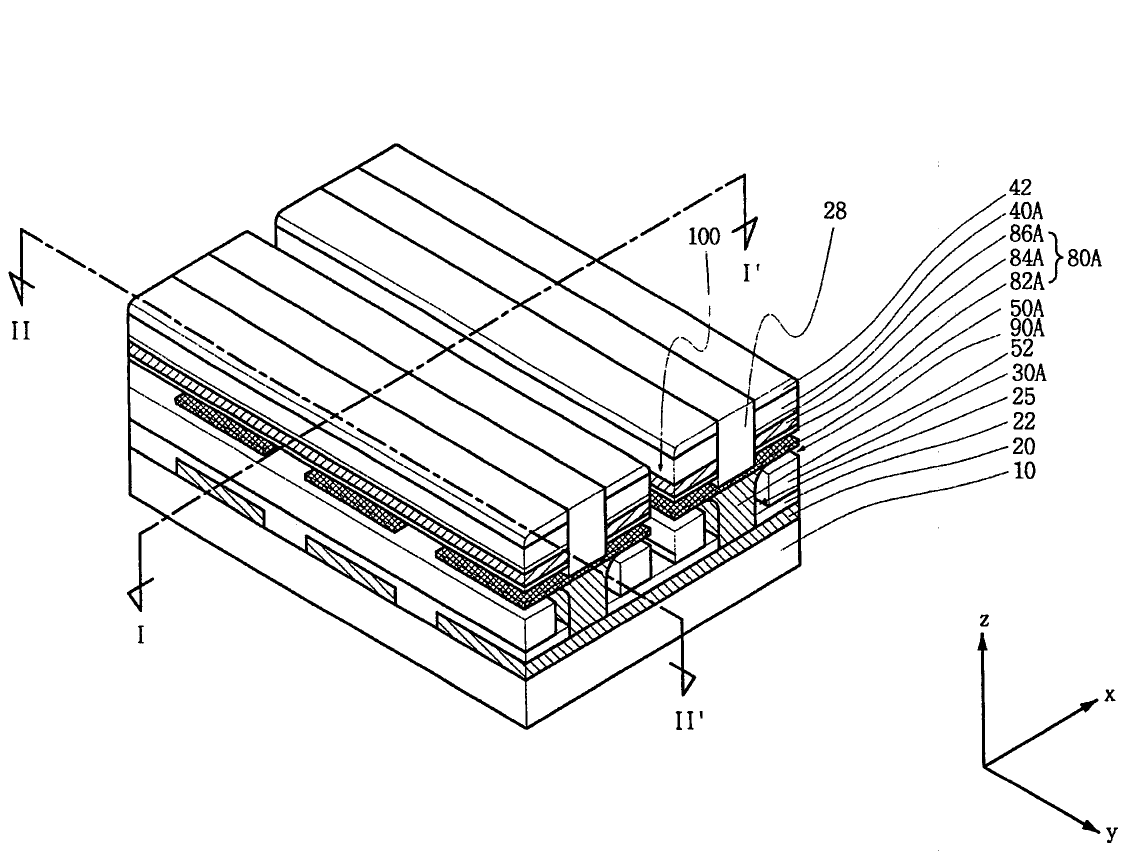
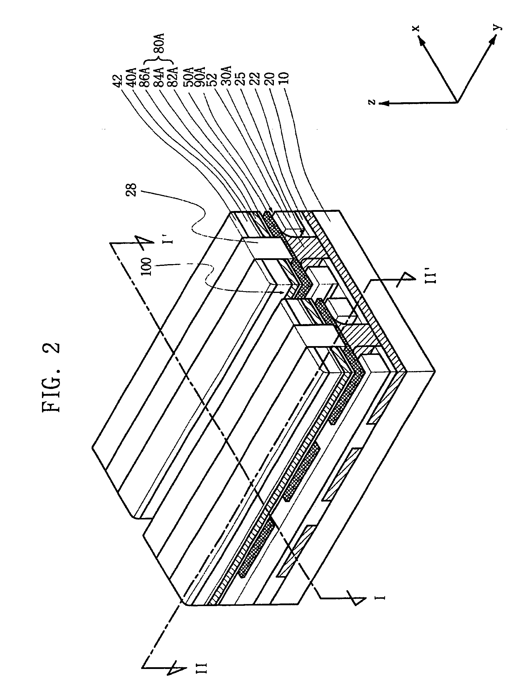
[0042]The present invention now will be described more fully hereinafter with reference to FIGS. 2 to 18, in which embodiments are shown. This invention may, however, be embodied in many different forms and should not be construed as limited to the embodiments set forth herein. Rather these embodiments are provided so that this disclosure will be thorough and complete, and will fully convey the scope of the invention to those skilled in the art.

[0043]Unless otherwise defined, all terms (including technical and scientific terms) used herein have the same meaning as commonly understood by one of ordinary skill in the art to which this invention belongs. It will be further understood that terms used herein should be interpreted as having a meaning that is consistent with their meaning in the context of this specification and the relevant art and will not be interpreted in an idealized or overly formal sense unless expressly so defined herein. Exemplary embodiments of the present invent...


PUM


Abstract

A multibit electro-mechanical memory device comprises a substrate, a bit line on the substrate, a first interlayer insulating film on the bit line, first and second lower word lines on the first interlayer insulating film, the first and second lower word lines separated horizontally from each other by a trench, a spacer abutting a sidewall of each of the first and second lower word lines, a pad electrode inside a contact hole, first and second cantilever electrodes suspended over first and second lower voids that correspond to upper parts of the first and second lower word lines provided in both sides on the pad electrode, the first and second cantilever electrodes being separated from each other by the trench, and being curved in a third direction that is perpendicular to the first and second direction; a second interlayer insulating film on the pad electrode, first and second trap sites supported by the second interlayer insulating film to have first and second upper voids on the first and second cantilever electrodes, and first and second upper word lines on the first and second trap sites.

Description

CROSS REFERENCE TO RELATED APPLICATIONS[0001]This application claims priority under 35 U.S.C. § 119 from Korean Patent Application No. 10-2007-0050223, filed on May 23, 2007, the contents of which are hereby incorporated by reference in their entirety for all purposes as if fully set forth herein.FIELD OF THE INVENTION[0002]The present invention relates to a semiconductor memory device and method of manufacturing the same. More particularly, the present invention relates to a multibit electro-mechanical memory device and a method of manufacturing the same, for programming and reading data by a switching operation performed by cantilever electrodes that are formed symmetrically relative to a trench.BACKGROUND OF THE INVENTION[0003]Typically, a memory device that stores data is largely classified as either a volatile semiconductor memory device or a nonvolatile semiconductor memory device. The volatile memory device principally represented as a DRAM (Dynamic Random Access Memory) or a...

Claims


Application Information

Patent Timeline
Patent Type & Authority Applications(United States)
IPC IPC(8): G11C16/00H01L27/00H01L21/00
CPCG11C11/50H01L27/115H01L27/10H10B69/00H10B99/00
Inventor YUN, EUN-JUNGKIM, MIN-SANGKIM, SUNG-MINLEE, SUNG-YOUNGLEE, JI-MYOUNGCHOI, IN-HYUK
Owner SAMSUNG ELECTRONICS CO LTD
Why Eureka
Try Eureka