Power and regasification system for LNG

a technology of power and regasification system, applied in the direction of machines/engines, mechanical equipment, containers, etc., can solve the problem of uneconomic transportation of natural gas through pipelines

Active Publication Date: 2009-04-23
ORMAT TECH INC
View PDF12 Cites 44 Cited by
  • Summary
  • Abstract
  • Description
  • Claims
  • Application Information

AI Technical Summary

Benefits of technology

[0009]Power is generated due to the large temperature differential between cold LNG, e.g. approximately −160° C., and the heat source of the vaporizer. The heat source of the vaporizer may be

Problems solved by technology

In some regions of the world, the transportation

Method used


Image

  • Power and regasification system for LNG
  • Power and regasification system for LNG
  • Power and regasification system for LNG

Examples


Embodiment Construction

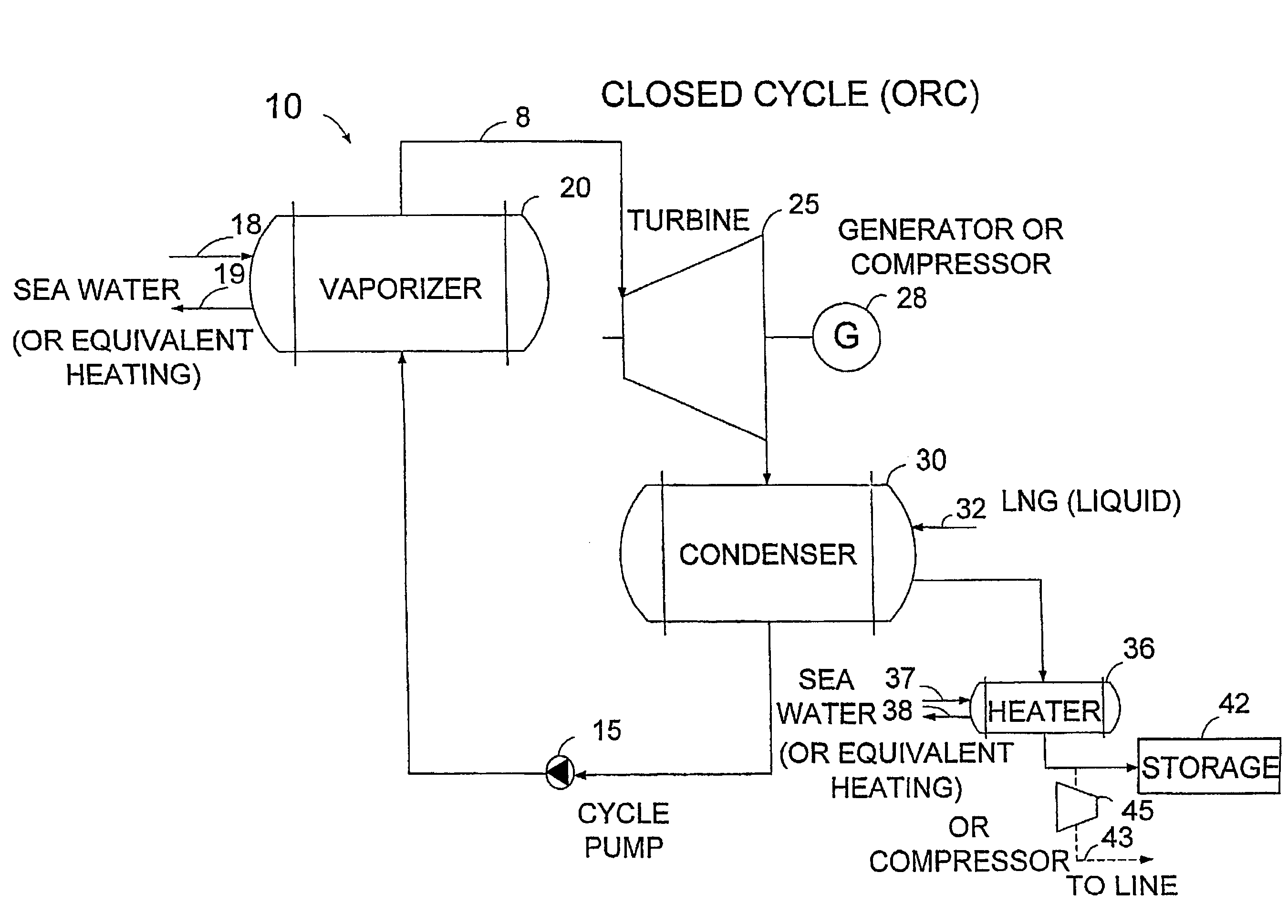
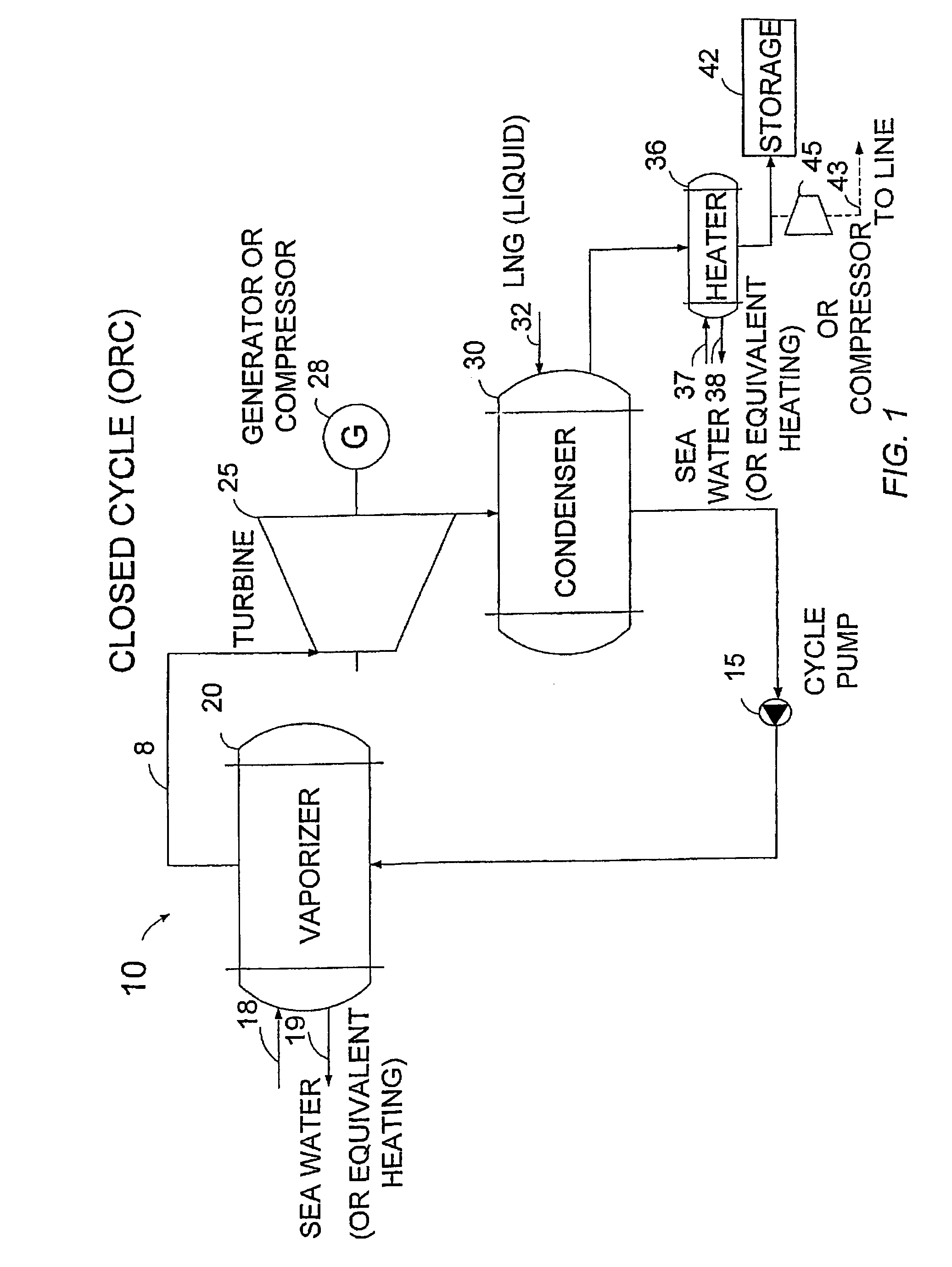
[0049]The present invention is a power and regasification system based on liquid natural gas (LNG). While transported LNG, e.g. mostly methane, is vaporized in the prior art at a regasification terminal by being passed through a beat exchanger, wherein sea water or another heat source e.g. the exhaust of a gas turbine heats the LNG above its boiling point, an efficient method for utilizing the cold LNG to produce power is needed. By employing the power system of the present invention, the cold temperature potential of the LNG serves as a cold sink of a power cycle. Electricity or power is generated due to the large temperature differential between the cold LNG and the heat source, e.g. sea water.

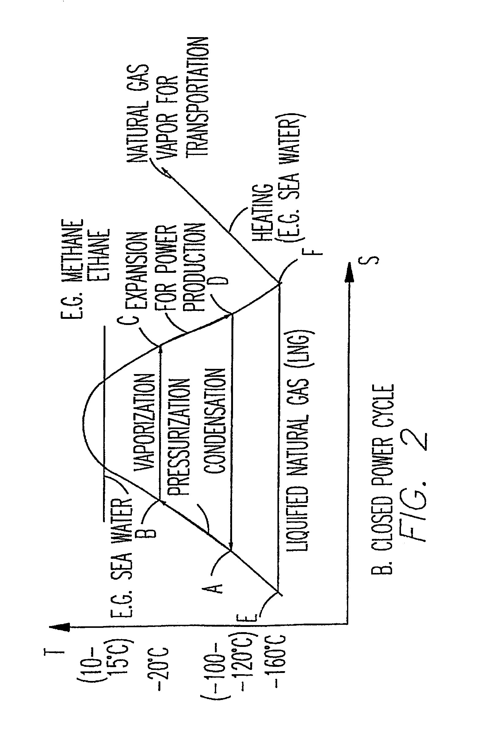
[0050]FIGS. 1 and 2 illustrate one embodiment of the invention, wherein cold LNG serves as the cold sink medium in the condenser of a closed Rankine cycle power plant. FIG. 1 is a schematic arrangement of the power system and FIG. 2 is a temperature-entropy diagram of the closed cycle.

[0051]...


PUM


Abstract

The present invention provides a power and regasification system based on liquefied natural gas (LNG), comprising a vaporizer by which liquid motive fluid is vaporized, said liquid motive fluid being LNG or a motive fluid liquefied by means of LNG; a turbine for expanding the vaporized motive fluid and producing power; heat exchanger means to which expanded motive fluid vapor is supplied, said heat exchanger means also being supplied with LNG for receiving heat from said expanded fluid vapor, whereby the temperature of the LNG increases as it flows through the heat exchanger means; a conduit through which said motive fluid is circulated from at least the inlet of said vaporizer to the outlet of said heat exchanger means; and a line for transmitting regasified LNG.

Description

FIELD OF THE INVENTION[0001]The present invention relates to the field of power generation. More particularly, the invention relates to a system which both utilizes liquefied natural gas for power generation and re-gasifies the liquefied natural gas.BACKGROUND OF THE INVENTION[0002]In some regions of the world, the transportation of natural gas through pipelines is uneconomic. The natural gas is therefore cooled to a temperature below its boiling point, e.g. −160° C., until becoming liquid and the liquefied natural gas (LNG) is subsequently stored in tanks. Since the volume of natural gas is considerably less in liquid phase than in gaseous phase, the LNG can be conveniently and economically transported by ship to a destination port.[0003]In the vicinity of the destination port, the LNG is transported to a regasification terminal, whereat it is reheated by heat exchange with sea water or with the exhaust gas of gas turbines and converted into gas. Each regasification terminal is usu...

Claims


Application Information

Patent Timeline
IPC IPC(8): F01K25/00
CPCF01K25/08F17C2265/07F17C2223/0123F17C2227/0135F17C2227/0157F17C2227/0309F17C2227/0311F17C2227/0318F17C2227/0323F17C2227/0327F17C2227/0388F17C2227/0393F17C2265/015F17C2265/05F17C2221/033
Inventor AMIR, NADAVBRONICKI, LUCIEN Y.REGAL, MEIR
Owner ORMAT TECH INC
Why Eureka
Try Eureka