Substrate cleaning apparatus

a cleaning apparatus and substrate technology, applied in the direction of cleaning process and apparatus, cleaning using liquids, chemistry apparatus and processes, etc., can solve the problems of back contamination of substrate w, reduce the yield of products, etc., and achieve the effect of preventing the production of water marks and preventing the back contamination of substra

Inactive Publication Date: 2009-04-23
EBARA CORP
View PDF5 Cites 23 Cited by
  • Summary
  • Abstract
  • Description
  • Claims
  • Application Information

AI Technical Summary

Benefits of technology

[0007]It is an object of the present invention to provide a substrate cleaning apparatus capable of preventing the production of the water marks on the surface of the substrate and preventing the back contamination of the substrate.
[0017]According to the present invention, since the spin cover rotates at substantially the same speed as the substrate, a relative speed between the substrate and the spin cover is substantially zero. Therefore, the cleaning solution hardly produce droplets and a mist when the cleaning solution impinges upon the spin cover. As a result, the production of the water marks and the back contamination of the substrate can be prevented. The cleaning solution, which is moved from the substrate to the spin cover, is quickly discharged downwardly along the inner circumferential surface of the spin cover under the centrifugal force. Therefore, the cleaning solution does not remain on the inner circumferential surface of the spin cover, and thus hardly produce the droplets and the mist thereof. As the relative speed between the substrate and the spin cover is substantially zero, almost no swirling flow of a gas is formed inside the spin cover. Consequently, the mist of the cleaning solution is prevented from being carried by the swirling flow of the gas and attached to the substrate.

Problems solved by technology

These water marks could adversely affect devices formed on the substrate W, resulting in a reduction in the yield of the products.
Use of a chemical solution as the cleaning solution, other than pure water, could also cause back contamination of the substrate W for the same reasons.

Method used


Image

  • Substrate cleaning apparatus
  • Substrate cleaning apparatus
  • Substrate cleaning apparatus

Examples


first embodiment

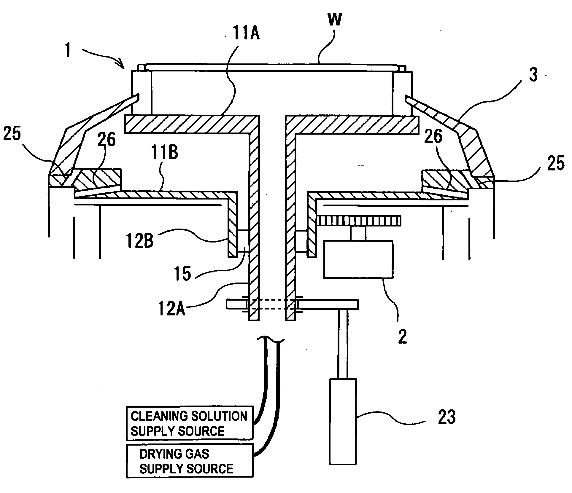
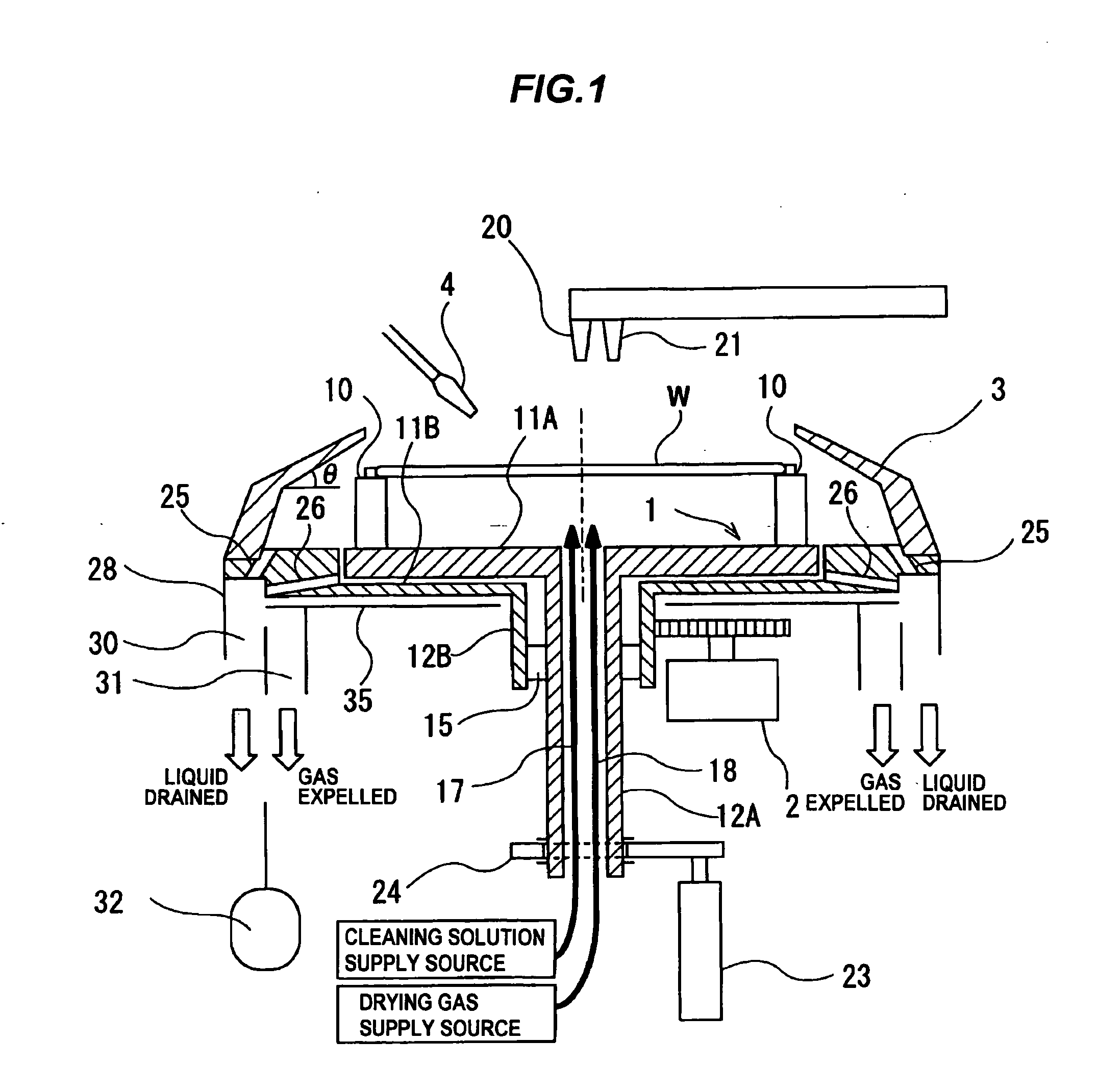
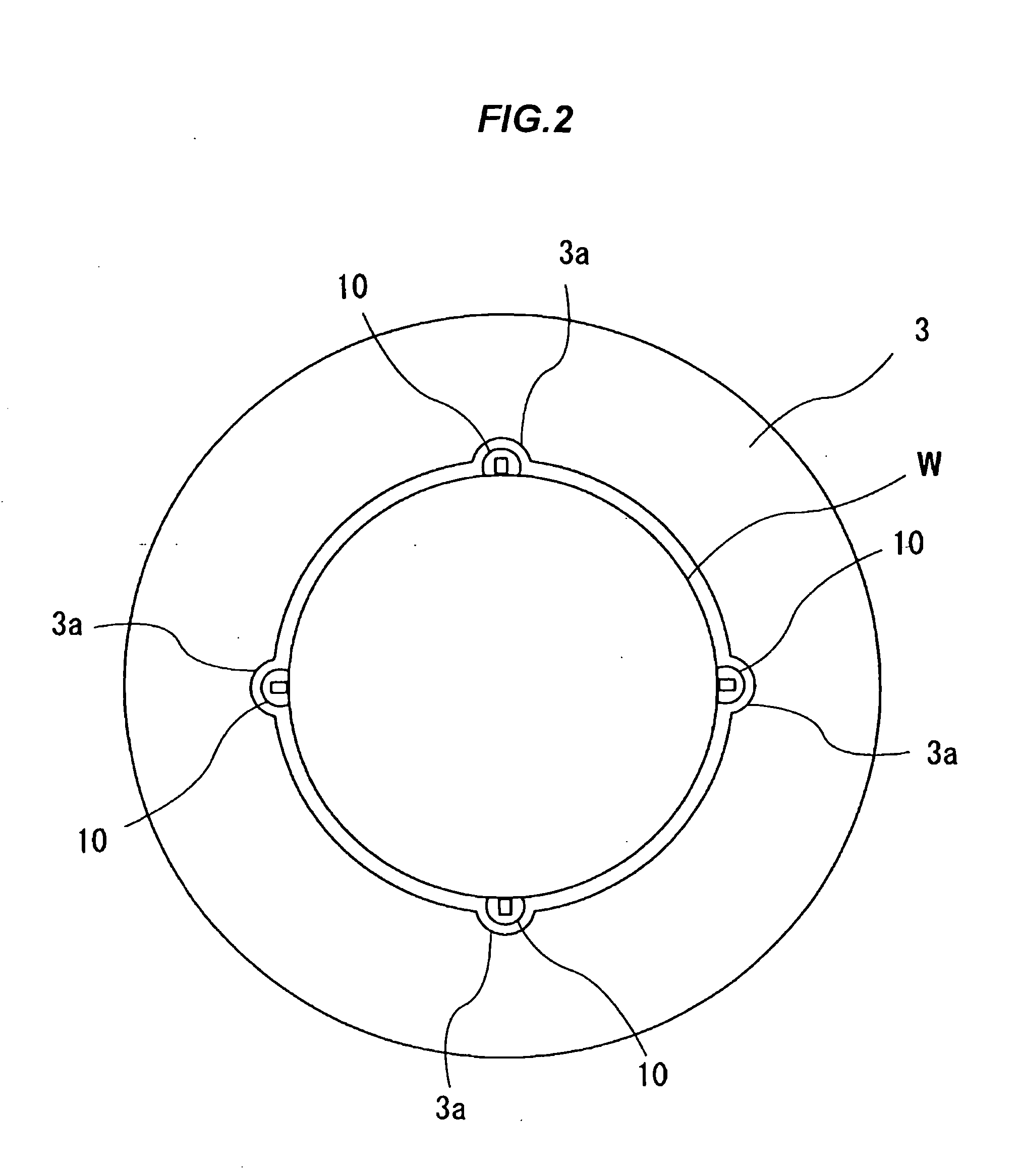
[0051]FIG. 1 is a schematic vertical cross-sectional view of a substrate cleaning apparatus according to the present invention, and FIG. 2 is a plan view of the substrate cleaning apparatus shown in FIG. 1.

[0052]As shown in FIG. 1, the substrate cleaning apparatus includes a substrate holding mechanism 1 configured to hold a substrate W horizontally, a motor (rotating mechanism) 2 configured to rotate the substrate W about its own central axis via the substrate holding mechanism 1, a spin cover 3 provided around the substrate W, and a front nozzle 4 for supplying pure water as a cleaning solution onto a surface (front surface) of the substrate W. A chemical solution, other than pure water, may be used as the cleaning solution.

[0053]The substrate holding mechanism 1 includes a plurality of chucks 10 configured to grip a peripheral edge of the substrate W, a circular first stage 11A on which the chucks 10 are mounted, a hollow first support shaft 12A supporting the first stage 11A, a ...

second embodiment

[0076] the substrate holding mechanism 1 includes a single stage 11, a hollow support shaft 12 supporting the stage 11, and a plurality of chucks 10 mounted on an upper surface of the stage 11. The spin cover 3 is fixed to a periphery of the stage 11. Relative position between the spin cover 3 and the substrate W is fixed at all times.

[0077]Below the stage 11, there are provided at least three push rods 40 and an actuator 23 for vertically moving these push rods 40. The stage 11 has a plurality of through-holes 11a in positions corresponding to positions of the respective push rods 40. The stationary plate 35, disposed beneath the stage 11, also has a plurality of through-holes (not shown) in positions corresponding to the positions of the respective through-holes 11a. The stage 11 has no auxiliary discharge holes.

[0078]The substrate W is dried in the same operational sequence as with the first embodiment. After the substrate W is dried, the actuator 23 elevates the push rods 40, as...

third embodiment

[0085]FIG. 14 is a schematic vertical cross-sectional view showing a modification of the substrate cleaning apparatus according to the present invention. As shown in FIG. 14, a plurality of fins 50 are fixed to the outer circumferential surface of the spin cover 3. The fins 50 can prevent the gas, that has flowed into the gap between the stationary cover 45 and the spin cover 3, from flowing back with the rotation of the spin cover 3. The outer circumferential surface of the spin cover 3 may have a spiral groove, instead of the fins 50, for causing the gas in the gap to flow downwardly by the rotation of the spin cover 3.

[0086]The stationary cover 45 according to the third embodiment may be applied to the substrate cleaning apparatus according to the first and second embodiments.

[0087]FIG. 15 is a schematic vertical cross-sectional view of a substrate cleaning apparatus according to a fourth embodiment of the present invention. Those parts of the substrate cleaning apparatus accordi...


PUM


Abstract

A substrate cleaning apparatus is used to clean a substrate with a cleaning liquid. The substrate cleaning apparatus includes a substrate holding mechanism configured to hold a substrate horizontally, a rotating mechanism configured to rotate the substrate held by the substrate holding mechanism, a liquid supply nozzle for supplying a cleaning solution to the substrate, and a spin cover provided around the substrate and rotatable at substantially the same speed as the substrate. The spin cover has an inner circumferential surface shaped so as to surround the substrate. The inner circumferential surface is, from a lower end to an upper end thereof, inclined radially inwardly.

Description

BACKGROUND OF THE INVENTION[0001]1. Field of the Invention[0002]The present invention relates to a substrate cleaning apparatus for cleaning a substrate by supplying a cleaning solution, such as pure water or a chemical solution, to the substrate, and drying the cleaned substrate.[0003]2. Description of the Related Art[0004]In the process of manufacturing semiconductor devices, cleaning of a substrate is an important process for increasing a yield of products. This substrate cleaning process is performed, for example, after a substrate polishing process to remove unwanted debris from the substrate. FIGS. 28 and 29 of the accompanying drawings show an example of a substrate cleaning apparatus. As shown in FIGS. 28 and 29, the substrate cleaning apparatus has a substrate holding mechanism 100 configured to hold a substrate W, a motor 101 configured to rotate the substrate holding mechanism 100, a stationary cover 102 provided around the substrate W, and a nozzle 103 for supplying pure...

Claims


Application Information

Patent Timeline
Patent Type & Authority Applications(United States)
IPC IPC(8): B08B3/04
CPCH01L21/67028H01L21/67051H01L21/6708H01L21/68785H01L21/67173H01L21/67219H01L21/68728H01L21/6715H01L21/304
Inventor MORISAWA, SHINYAMATSUDA, NAOKIKOJIMA, YASUSHI
Owner EBARA CORP
Why Eureka
Try Eureka