System and method for 3D measurement and surface reconstruction

a technology of surface reconstruction and measurement system, applied in the field of reconfigurable vision system and method, can solve the problems of slow measurement process, limited acquisition speed, and lack of ability of existing systems to change their settings, and achieve the effect of high speed

Inactive Publication Date: 2009-04-23
CITY UNIVERSITY OF HONG KONG
View PDF1 Cites 84 Cited by
  • Summary
  • Abstract
  • Description
  • Claims
  • Application Information

AI Technical Summary

Benefits of technology

[0029]An advantage of one or more preferred embodiments of the invention system is that the 3D information of a scene may be acquired at high speed by taking a single picture of the scene.
[0030]With this method, a complex 3D shape may be divided into a series of cross section curves, each of which represents the local geometrical feature of the object. These cross section curves may be described by a set of parametric equations. For reconstruction purposes using parametric equations, the most common methods include spline function (e.g. B-spline) [43], implicit polynomial [44], [45] and superquadric (e.g. superellipsoid). [46]. Compared with implicit polynomial and superquadric, B-spline has the following main advantages:1. Smoothness and continuity, which allows a curve to consist of a concatenation of curve segments, yet be treated as a single unit;2. Built-in boundedness, a property which is lacking in implicit or explicit polynomial representations whose zero set can shoot to infinity;3. Parameterized representation. which decouples the x, y coordinates enabling them to be treated separately;

Problems solved by technology

Currently, the devices widely used in industry for obtaining 3D measurements involve the mechanical scanning of a scene, for example in a laser scanning digitizer, which inevitably makes the measurement a slow process.
However, the existing systems lack the ability to change their settings, to calibrate by themselves and to reconstruct the 3D scene automatically.
The first issue is how to acquire the 3D data for reconstructing the object surface.
However, due to the mechanical scanning involved, the acquisition speed is limited.
The second issue is how to determine the next viewpoint for each view so that all the information about the object surface can be acquired in an optimal way.
In general, there are two fundamental problems to be solved when determining the Next Best View.
The first problem is to determine the areas of the object which need to be sensed next and the second is to determine how to position the sensor to sample those areas.
As there is no prior knowledge about the object, it is impossible to obtain a complete description of an object when occlusion occurs.
Therefore, it is not generally possible to obtain precisely the invisible portions from either the current viewpoint or the acquired partial description of the object, so only an estimation of the Next Best View may be derived.
This algorithm is computationally expensive and it does not incorporate the sensor geometry.
However, this solution is limited to a particular sensor configuration.
However, the superellipsoid cannot accurately represent objects with a complex surface shape.
Furthermore, surface visibility constraints were not incorporated in the viewpoint planning process.
The algorithm involves expensive computation on the solid modeling and intersection operation.
A traditional vision sensor with fixed structure is often inadequate for the robot to perceive the object's features in an uncertain environment as the object distance and size are unknown before the robot sees the object.
This assumption limits the range of applications of this method.
How to obtain a suitable initialization was still an issue to solve [31].
As a result, they suffer from the ambiguity of correspondences between the camera images, which is a difficult problem to solve especially when free-form surfaces [33] are involved in the scene.
As a result, the applications of active vision systems are limited, since the system configuration and parameters must be kept unchanged during the entire measurement process.
The available camera self-calibration methods cannot be applied directly to structured-light systems as they need more than two views for the calibration.
The limitation of this method is that the object must be placed on a special device so that it can be precisely moved.
In such applications, uncalibrated reconstruction is needed.
However, it was not clear how many of the parameters of the camera and projector could be self-determined in the uncalibrated reconstruction process.

Method used


Image

  • System and method for 3D measurement and surface reconstruction
  • System and method for 3D measurement and surface reconstruction
  • System and method for 3D measurement and surface reconstruction

Examples


Embodiment Construction

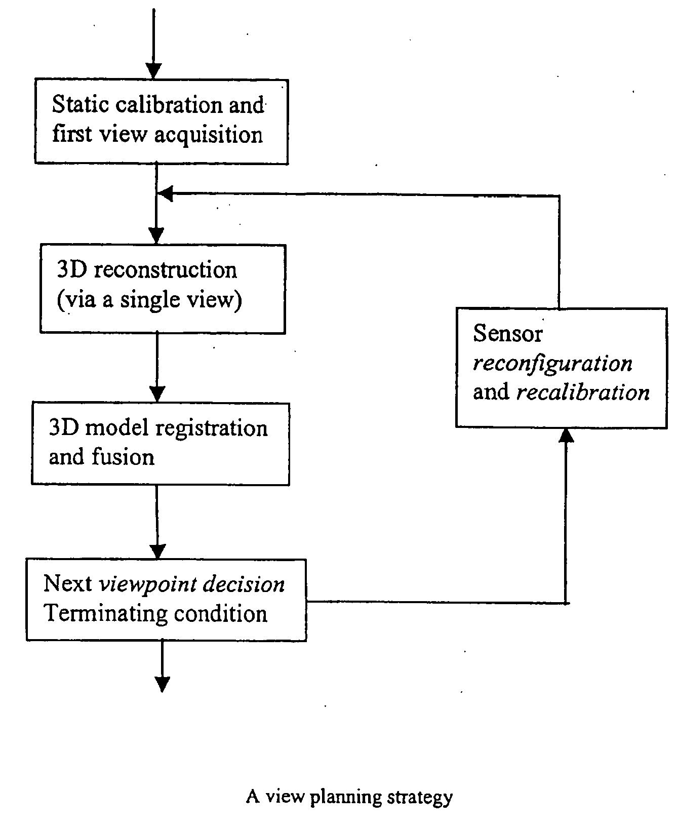
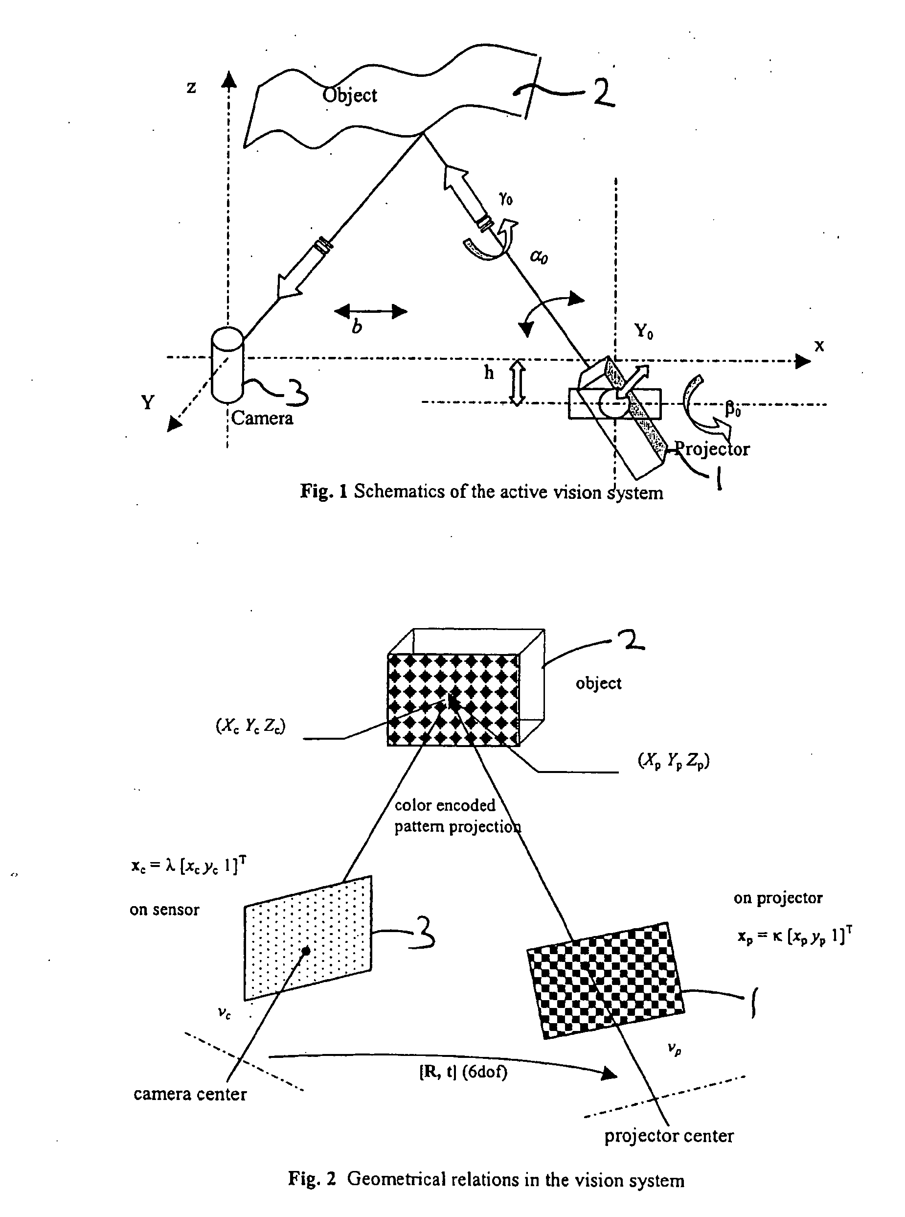
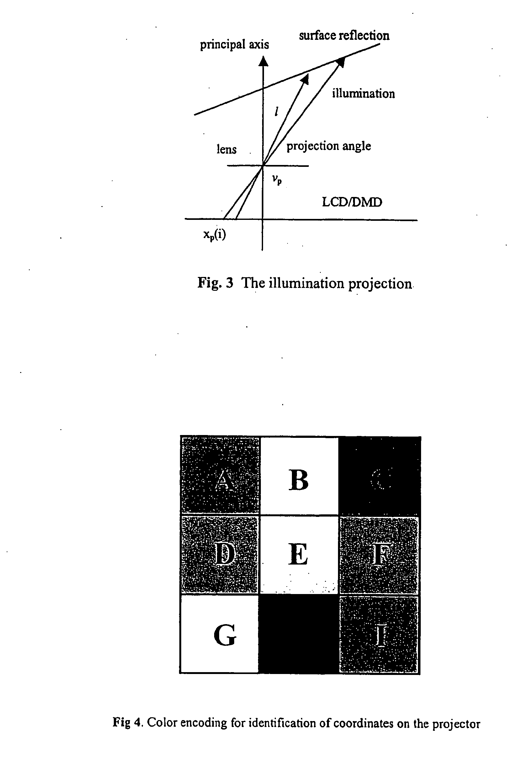
[0045]FIG. 1 shows an active vision system according to a preferred embodiment of the invention. The system comprises an LCD projector 1 adapted to cast a pattern of light onto an object 2 which is then viewed by a camera and processor unit 3. The relative position between the projector 1 and the camera in the camera and processing unit 3 has six degrees of freedom (DOF). When a beam of light is cast from the projector 1 and viewed obliquely by the camera, the distortions in the beam line may be translated into height variations via triangulation if the system is calibrated including the relative position between the projector 1 and camera. The vision system may be self-recalibrated automatically if and when this relative position is changed. The camera and processor unit 3 preferably includes a processor stage, as well as the camera, for processing the observed distortions in the projected pattern caused by the object 2 and associated data and for enabling and carrying out reconstr...


PUM


Abstract

A system and method for measuring and surface reconstruction of a 3D image of an object comprises a projector arranged to project a pattern onto a surface of an object to be imaged; and a processor stage arranged to examine distortion or distortions produced in the pattern by the surface. The processor stage is arranged to convert by, for example, a triangulation process the distortion or distortions produced in the pattern by the surface to a distance representation representative of the shape of the surface. The processor stage is also arranged to reconstruct electronically the surface shape of the object.

Description

FIELD OF THE INVENTION[0001]The present invention relates to a system and method for 3D measurement and surface reconstruction of an image reconfigurable vision, and in particular to a reconfigurable vision system and method.BACKGROUND OF THE INVENTION[0002]In many practical applications, such as reverse engineering, robotic exploration / navigation in clustered environments, model construction for virtual reality, human body measurements, and advanced product inspection and manipulation by robots, the automatic measurement and reconstruction of 3D shapes with high speed and accuracy is of critical importance. Currently, the devices widely used in industry for obtaining 3D measurements involve the mechanical scanning of a scene, for example in a laser scanning digitizer, which inevitably makes the measurement a slow process. Some advanced active vision systems using structured lighting have been explored and built. However, the existing systems lack the ability to change their setting...

Claims


Application Information

Patent Timeline
Patent Type & Authority Applications(United States)
IPC IPC(8): G06T17/00
CPCG01B11/2504G01B11/2509G06T17/10G06T7/0057G06T7/0018G06T7/80G06T7/521
Inventor LI, YOU FU
Owner CITY UNIVERSITY OF HONG KONG
Why Eureka
Try Eureka