System for delivering air from a multi-stage compressor to a turbine portion of a gas turbine engine

a gas turbine engine and multi-stage compressor technology, applied in the direction of machines/engines, combination engines, liquid fuel engines, etc., can solve the problems of inefficient use of high pressure extraction air, ineffective cost-effectiveness of combining high and low pressure air, and insufficient pressure for medium and low pressure extraction. , to achieve the effect of reducing the fuel bum rate, reducing the cost of fuel consumption and increasing the output of generators

Active Publication Date: 2009-04-23
GENERAL ELECTRIC CO
View PDF10 Cites 57 Cited by
  • Summary
  • Abstract
  • Description
  • Claims
  • Application Information

AI Technical Summary

Benefits of technology

[0008]Surprisingly however, it has been found that routing the high pressure extraction to the low pressure turbine input will cause higher than design pressure ratios on the low pressure input. The increase in air to the low pressure input results in less air being passed to a combustor in the turbine engine. With less air being passed to the combustor, less fuel is required to maintain combustor firing temperature within emissions compliance. Using less fuel also lowers fuel bum rate and, as a consequence, plant output can be lowered to a level beyond what is

Problems solved by technology

During non-optimal operating conditions, high pressure bypass extraction air is delivered from the high pressure compressor extraction to both the high pressure input port and the low pressure input port on the turbine.
However, the medium and low pressure extractions no longer have enough pressure to adequately supply the respective medium and low pressure turbine

Method used


Image

  • System for delivering air from a multi-stage compressor to a turbine portion of a gas turbine engine
  • System for delivering air from a multi-stage compressor to a turbine portion of a gas turbine engine

Examples


Embodiment Construction

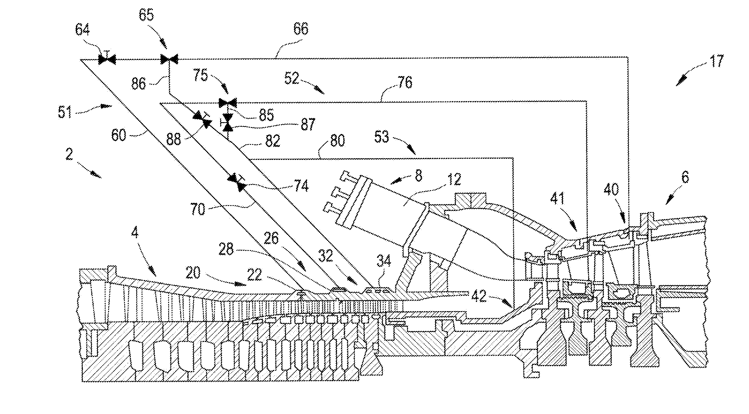
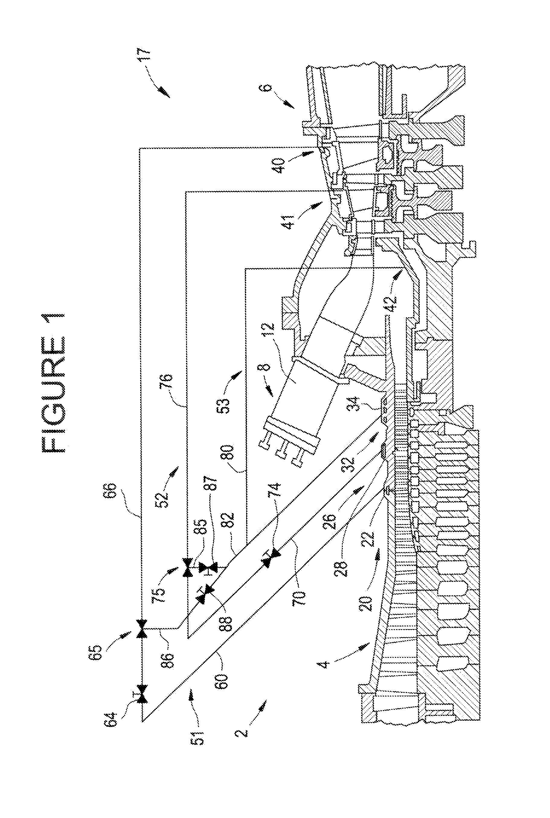
[0011]With initial reference to FIG. 1, a gas turbine engine constructed in accordance with an exemplary embodiment of the present invention is generally indicated at 2. Engine 2 includes a compressor 4 operatively connected to a turbine 6 via a shaft (not separately labeled). Engine 2 is further shown to include a combustor assembly 8 including a combustion chamber 12. Combustion gases are produced in combustor assembly 8 and used to drive turbine 6 as will be discussed more fully below.

[0012]In operation, air flows into compressor 4 and is compressed into a high pressure gas. The high pressure gas is supplied to combustor assembly 8 and mixed with fuel, for example process gas and / or synthetic gas (syngas). The fuel / air or combustible mixture is passed into combustion chamber 12 and is ignited to form a high pressure, high temperature combustion gas stream of approximately 871° Celsius (C.) to 1621° C. (1600° Fahrenheit (F.) to 2950° F.). Alternatively, combustor assembly 8 can co...


PUM


Abstract

A system for providing air from a multi-stage to a turbine includes a turbine having a high pressure input port and a low pressure input port. The system also includes a compressor having at least one high pressure extraction air output and at least one low pressure extraction air output. A valve is fluidly connected to the at least one high pressure extraction air output, at least one low pressure extraction air output and low pressure input port of the turbine. The valve is selectively operated to fluidly connect the at least one low pressure extraction air output with the low pressure input port during normal operating conditions and fluidly connect the at least one high pressure extraction air output and the low pressure input port during a turn down condition or below design temperature operation to enhance turbine engine performance.

Description

BACKGROUND OF THE INVENTION[0001]The present invention pertains to the art of gas turbine engines and, more particularly, to a system for delivering air from a multi-stage compressor to a turbine portion of a gas turbine engine to enhance turbine engine performance during low turn down and / or operation below design temperatures.[0002]Turbine engines are designed to operate at full speed, International Organization for Standardization (ISO) conditions. That is, turbine engines are designed to utilize a defined range of input conditions, e.g., design point temperature, barometric pressure, fuel type etc, to operate within a defined speed band to produce an optimal, high, output below which operation is less than efficient. Often times however, input conditions are outside the design points, and / or a lower than full output is desired. During ISO operation, air is fed into a combustor to mix with fuel to form a high pressure, high temperature combustion product that is delivered to the ...

Claims


Application Information

Patent Timeline
IPC IPC(8): F01B25/22
CPCF01D25/12F02C6/08
Inventor ROUSH, ERIC DAVIDPARKER, WILLIAM ANDREW
Owner GENERAL ELECTRIC CO
Why Eureka
Try Eureka