Hydrogen production system and method of controlling flow rate of offgas in the system

a technology of hydrogen production system and offgas flow, which is applied in the direction of liquid-gas reaction process, process and machine control, hydrogen separation using solid contact, etc., can solve the problem of inability to continuously discharge offgas, decrease in the amount of offgas discharged from the adsorption tower, and decrease in the concentration of hydrogen in the offgas. , to avoid the effect of changing the supply flow

Inactive Publication Date: 2009-04-23
SUMITOMO SEIKA CHEM CO LTD
View PDF5 Cites 9 Cited by
  • Summary
  • Abstract
  • Description
  • Claims
  • Application Information

AI Technical Summary

Benefits of technology

[0012]The present invention has been proposed under the above-described circumstances, for a hydrogen manufacturing system in which a vaporizer uses off gas as a fuel for heating the mixed material before supplied to the reformer, where the offgas was discharged from a pressure swing adsorption gas separato...

Problems solved by technology

However, as time passes in the desorption process, the amount of offgas discharged from the adsorption tower decreases and the hydrogen concentration in the offgas also decreases.
Further, in the PSA separation method, it is sometimes impossible to discharge the offgas continuously due to adsorption tower operation cycle limitations.
Therefore, if the offgas from the adsorption tower is continuously supplied via the piping at an uncontrolled pace, the amount of hydrogen gas in the offgas supplied to the vaporizer changes relatively widely over time, resulting in unstable combustion in the vaporizer.
However, under such a control, with regard to the amount of raw material mixture supply to the vaporizer and the flow of offgas, while the amount of raw material mixture supply is increased continuously, the offgas...

Method used


Image

  • Hydrogen production system and method of controlling flow rate of offgas in the system
  • Hydrogen production system and method of controlling flow rate of offgas in the system
  • Hydrogen production system and method of controlling flow rate of offgas in the system

Examples


Embodiment Construction

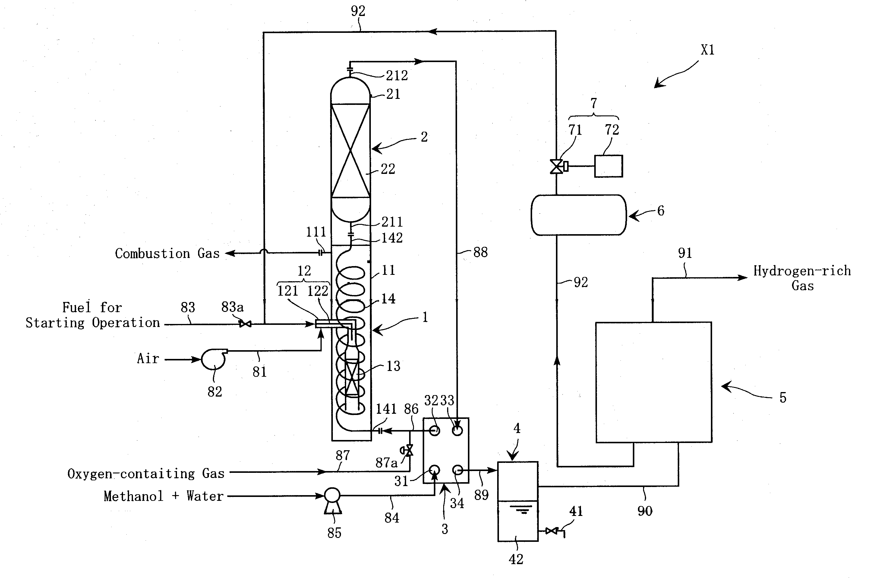
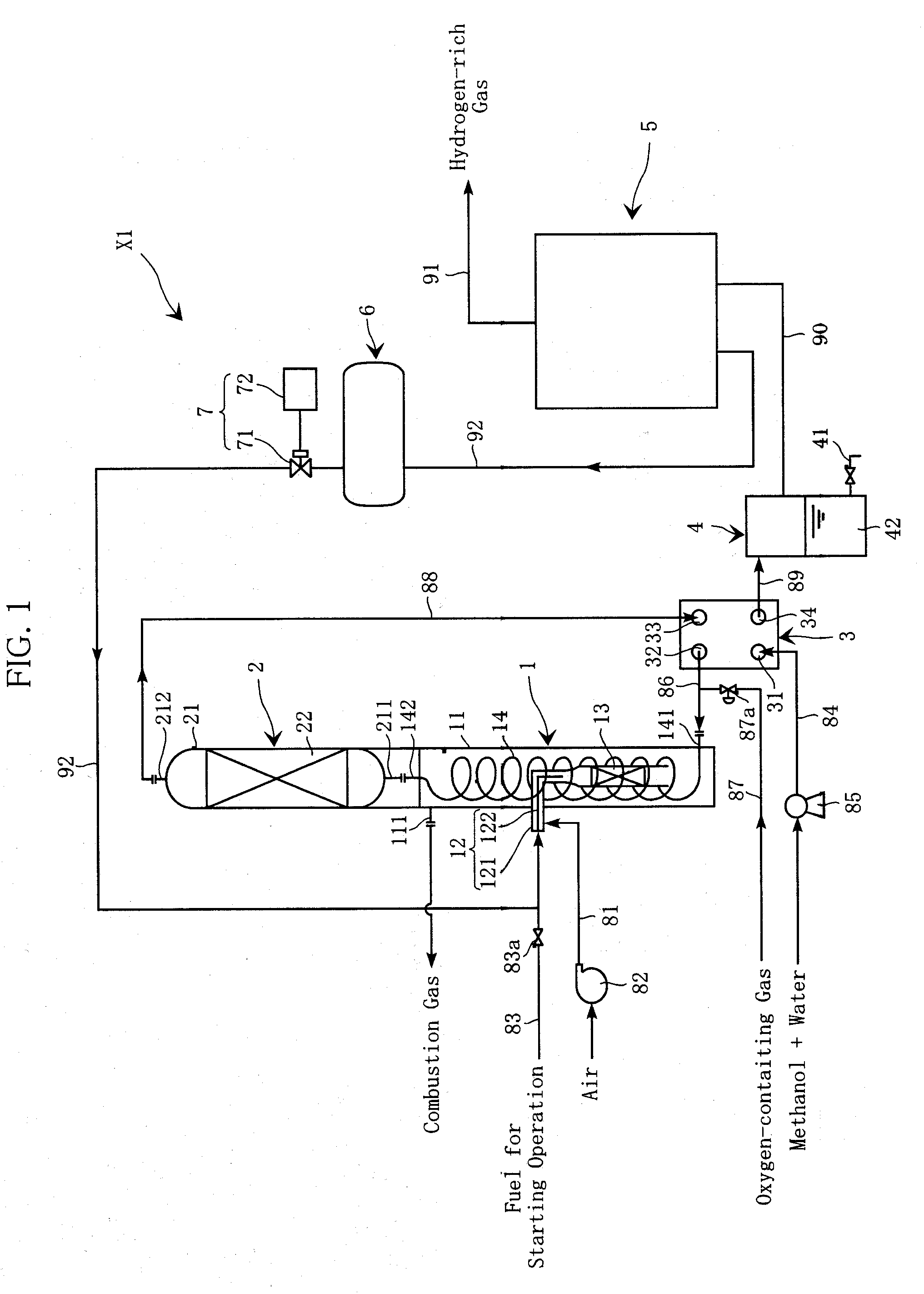
[0030]FIG. 1 is a schematic diagram of a hydrogen manufacturing system X1 which can be used for performing an offgas flow controlling method according to the present invention. The hydrogen manufacturing system X1 includes a vaporizer 1, a reforming reactor 2, a heat exchanger 3, a gas-liquid separator 4, a pressure swing adsorption gas separator (PSA separator) 5, a buffer tank 6 and an offgas flow controlling unit 7, and is configured to manufacture hydrogen from methanol as a principal hydrocarbon raw material.

[0031]The vaporizer 1, which includes a main container 11, a supply pipe 12, a catalytic combustion section 13 and a distribution pipe 13, is a place where a material mixture which includes methanol, water and oxygen is heated into a vaporized state. FIG. 1 shows internal structure of the vaporizer 1 in a schematic manner.

[0032]The main container 11 has a structure as a closed tube, having an upper end provided with a combustion gas discharge port 111. The supply pipe 12 ha...


PUM


Abstract

A hydrogen manufacturing system for performing offgas flow control includes: a vaporizer (1) for heating a material mixture containing a hydrocarbon material; a reforming reactor (2) for generating hydrogen-containing reformed gas by reforming reactions of the material; a PSA separator (5) for repeating a cycle of adsorption and desorption, where in the adsorption PSA separation is performed with an adsorption tower loaded with an adsorbent to adsorb unnecessary components in the reformed gas and extract hydrogen-enriched gas out of the tower, and in the desorption the offgas containing the unnecessary components from the adsorbent and remaining hydrogen is discharged from the tower; and a buffer tank (6) for holding the offgas before supplying to the vaporizer. The offgas flow supply from the tank (6) to the vaporizer is changed continuously over time when the cycle time is changed according to load change on the separator (5).

Description

TECHNICAL FIELD[0001]The present invention relates to a hydrogen manufacturing system for industrially manufacturing hydrogen from a hydrocarbon raw material. Further, the present invention relates to an offgas flow controlling method for the hydrogen manufacturing system.BACKGROUND ART[0002]Hydrogen (high-purity hydrogen) is used in a number of industrial fields such as metal heat treatment, glass melting, semiconductor manufacturing and optical fiber manufacturing. Hydrogen is also used as fuel for fuel cells.[0003]A hydrogen manufacturing system for industrially manufacturing hydrogen is disclosed in the following Patent Document 1 for example. The hydrogen manufacturing system disclosed in Patent Document 1 includes a vaporizer, a reforming reactor and a pressure swing adsorption gas separator. The vaporizer heats and vaporizes a raw material mixture, which contains a hydrocarbon raw material such as methanol and natural gas, water and oxygen, before it is supplied to the reform...

Claims


Application Information

Patent Timeline
IPC IPC(8): B01D53/053G05D7/00G05D7/06B01J7/00
CPCB01D53/047Y02E60/50B01D2257/108C01B3/32C01B3/323C01B3/56C01B2203/0233C01B2203/0244C01B2203/043C01B2203/0495C01B2203/0822C01B2203/0827C01B2203/0872C01B2203/0888C01B2203/1041C01B2203/1064C01B2203/107C01B2203/1076C01B2203/1223C01B2203/1288C01B2203/1695H01M8/0631H01M8/0662B01D2256/16Y10T137/0357Y02P20/10C01B3/38
Inventor SUMIDA, TOSHIHIKOMIYAKE, MASANORIMINAMI, HIDENORIUEDA, YOSHINORI
Owner SUMITOMO SEIKA CHEM CO LTD
Why Eureka
Try Eureka