Steering system

a steering system and variable transfer ratio technology, applied in the direction of steering initiation, instruments, vessel construction, etc., can solve the problems of electric power steering unit, variable force, difficult turning of steering wheel of steering system provided with such variable transfer ratio mechanism, etc., to reduce electric current and comfortable wheel steering

Active Publication Date: 2009-04-23
HONDA MOTOR CO LTD
View PDF8 Cites 45 Cited by
  • Summary
  • Abstract
  • Description
  • Claims
  • Application Information

AI Technical Summary

Benefits of technology

[0034]According to a fifth aspect of the invention, the steering system that changes the transfer ratio of the steering angle of the steering wheel to the turning angle of the turning wheel by means of the variable transfer ratio mechanism and generates auxiliary power during steering by means of the electric power steering unit includes a transfer ratio modulating and setting section for setting a rotational angle of the transfer ratio variable motor used in the variable transfer ratio mechanism so that the transfer ratio is set at a target transfer ratio corresponding to vehicle speed and a steering torque modulating and setting section of reducing an electric current for driving the transfe

Problems solved by technology

If the driver tries to turn the steering wheel quickly when the ratio is quickened in the low vehicle speed range, the steering wheel of the steering system provided with such variable transfer ratio mechanism and electric power steering unit may become tough to turn because deficiency of thrust force occurs due to an influence of counter electromotive voltage of an EPS (Electric Power Steering) motor, i.e., a power source of the electric power steering unit, even through the electric power steering unit tries to generate the auxiliary power so as to be able to turn the turning wheel largely and quickly.
However, the prior art method was considered to cause such phenomena that steering reactive force fluctuates as if it undulates with respect to such steering operations of quick-slow-quick for example or

Method used


Image

  • Steering system
  • Steering system
  • Steering system

Examples


first embodiment

(Steering System)

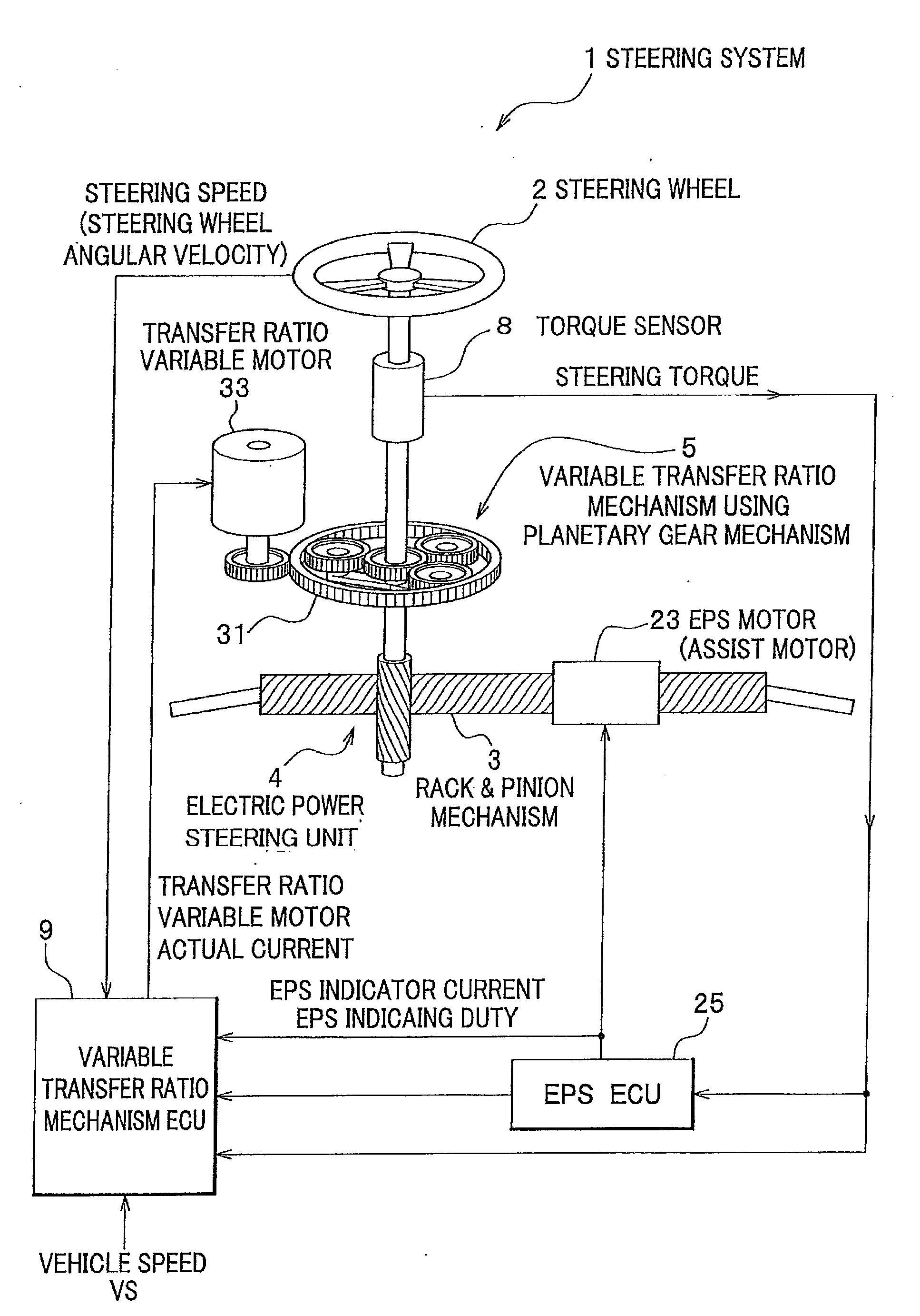
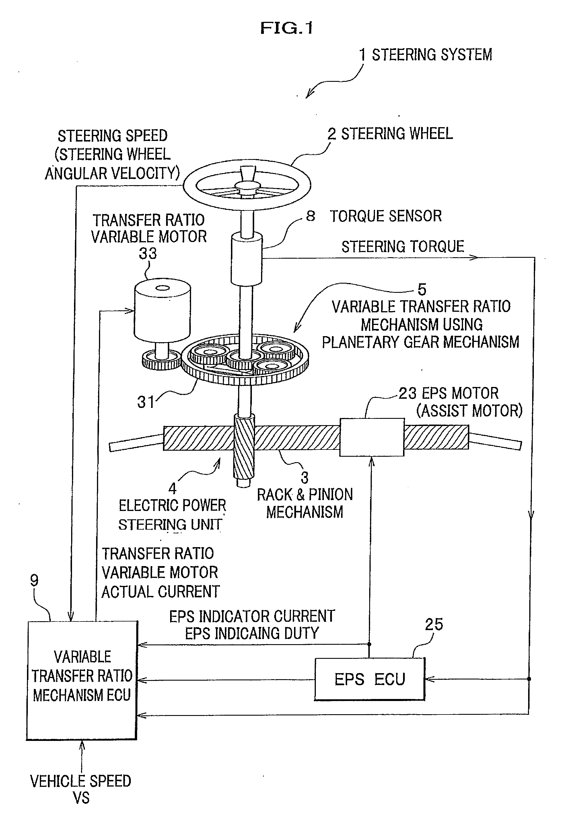
[0071]FIG. 1 shows an overall schematic structure of a steering system 1 according a first embodiment of the invention.

[0072]As shown in FIG. 1, the steering system 1 includes a steering wheel 2, a rack & pinion mechanism 3, an electric power steering unit 4, a variable transfer ratio mechanism 5 using a planetary gear mechanism (differential gear) 31 and a torque sensor 8.

[0073]The variable transfer ratio mechanism 5 has the planetary gear mechanism 31 as the differential gear linked respectively with a rotary shaft of the steering wheel 2 and a rack & pinion mechanism 3, a transfer ratio variable motor 33 for turning a ring gear of the planetary gear 31 to change a transfer ratio of a steering angle of the steering wheel 2 with respect to a turning angle of a turning wheel not shown and a variable transfer ratio mechanism controlling ECU 9 for controlling the transfer ratio variable motor 33 by flowing actual current for driving the transfer ratio variable motor 3...

second embodiment

[0122]Next, a steering system of a second embodiment of the invention will be explained with reference to FIGS. 6 through 9. Note that the second embodiment will be explained mainly on differences thereof from the first embodiment. Still more, although the variable transfer ratio controlling ECU will be denoted as a variable transfer ratio mechanism controlling ECU 9A (see FIG. 7) in the second embodiment as described later, as a variable transfer ratio mechanism controlling ECU 9B (see FIG. 11) in a third embodiment and as a variable transfer ratio mechanism controlling ECU 9C (see FIG. 15) in a fourth embodiment, the ECU will be denoted typically as a variable transfer ratio mechanism controlling ECU 9 here.

[0123]As shown in FIG. 6, the torque sensor 8 is provided between the steering wheel 2 and the planetary gear mechanism 31 to detect steering torque applied to the steering wheel 2 and inputs a steering torque value Th to the EPS ECU 25. The torque sensor 8 also inputs the stee...

third embodiment

[0210]Next, the steering system of a third embodiment of the invention will be explained with reference to FIGS. 15 through 18 and to FIG. 6 as necessary.

[0211]FIG. 15 is a functional structural block diagram of the variable transfer ratio mechanism controlling ECU in a steering system of the third embodiment, FIG. 16 is a detailed functional structural block diagram of the target motor angle setting section and FIG. 17 is a flowchart showing a flow of control for correcting a target pinion angle in the target motor angle setting section.

[0212]FIG. 18A is a graph showing a temporal transition of an actual motor angle θvm and a target motor angle θTvm of the transfer ratio variable motor according to a comparative example and FIG. 18B is a graph showing a temporal transition of the actual motor angle θvm and the target motor angle θTvm of the transfer ratio variable motor of the third embodiment.

[0213]The steering system 1 of the third embodiment is different from the second embodime...


PUM


Abstract

There is provided a steering system allowing a comfortable steering operation even if a driver quickly turns a steering wheel when a transfer ratio is quickened in a low vehicle speed range. In the steering system that changes the transfer ratio of a steering angle of the steering wheel to a turning angle of a turning wheel by a variable transfer ratio mechanism and generates auxiliary power by an electric power steering unit, a variable transfer ratio mechanism controlling ECU has a switching section for switching a transfer ratio modulating mode of setting a rotational angle of a transfer ratio variable motor used in the variable transfer ratio mechanism so that the transfer ratio is set at a target transfer ratio corresponding to vehicle speed with a steering torque modulating mode of reducing an electric current for driving the motor so as to reduce steering power of the steering wheel.

Description

CROSS REFERENCE TO RELATED APPLICATIONS[0001]This application claims the foreign priority benefit under Title 35, United States Code, §119 (a)-(d) of Japanese Patent Application No. 2007-272048, filed on Oct. 19, 2007 and Japanese Patent Application No. 2008-156231, filed on Jun. 16, 2008 in the Japan Patent Office, the disclosure of which is herein incorporated by reference in its entirety.BACKGROUND OF THE INVENTION[0002]1. Field of the Invention[0003]The present invention relates to a steering system that changes a transfer ratio of a steering angle of a steering wheel to a turning angle of a turning wheel by means of a variable transfer ratio mechanism and generates auxiliary power during steering by means of an electric power steering unit.[0004]2. Description of Related Art[0005]Heretofore, a steering system having a variable transfer ratio mechanism and an electric power steering unit has been proposed. The variable transfer ratio mechanism enables a driver to largely turn a ...

Claims


Application Information

Patent Timeline
IPC IPC(8): B62D6/00
CPCB62D5/008B62D6/002B62D5/0472
Inventor YAMAGUCHI, TAKUYAAKUTA, YOSHIMITSU
Owner HONDA MOTOR CO LTD
Why Eureka
Try Eureka