Cogeneration system

a cogeneration system and cogeneration technology, applied in the direction of lighting and heating apparatus, heating types, sustainable manufacturing/processing, etc., can solve the problem that the cogeneration system cannot supply electric energy when required, and achieve the effect of low running cost, saving equipment cost and easy construction

Active Publication Date: 2009-04-30
HONDA MOTOR CO LTD
View PDF10 Cites 21 Cited by
  • Summary
  • Abstract
  • Description
  • Claims
  • Application Information

AI Technical Summary

Benefits of technology

[0009]Preferably, the first cooling device includes a first bypass pipe branching off the cooling water circulation path and then returning to the cooling water circulation path, a first radiator disposed in the first bypass pipe for radiating heat from the cooling water to the outside of the second bypass pipe, a first pump disposed in the first bypass pipe for feeding the cooling water into the first radiator, and a pair of first water supply valves disposed between the cooling water circulation path and the first radiator and adapted to open to thereby allow the cooling water to be introduced into the first radiator. The second cooling device includes a second bypass pipe branching off the hot water circulation pipe and then returning to the hot water circulation pipe, a second radiator disposed in the second bypass pipe for radiating heat from the hot water to the outside of the second bypass pipe, a second pump disposed in the second bypass pipe for feeding the hot water into the second radiator, and a pair of second water supply valves disposed between the hot...

Problems solved by technology

However, with the gas engine thus stopped, the cogeneration system cannot su...

Method used


Image

  • Cogeneration system
  • Cogeneration system
  • Cogeneration system

Examples


first embodiment

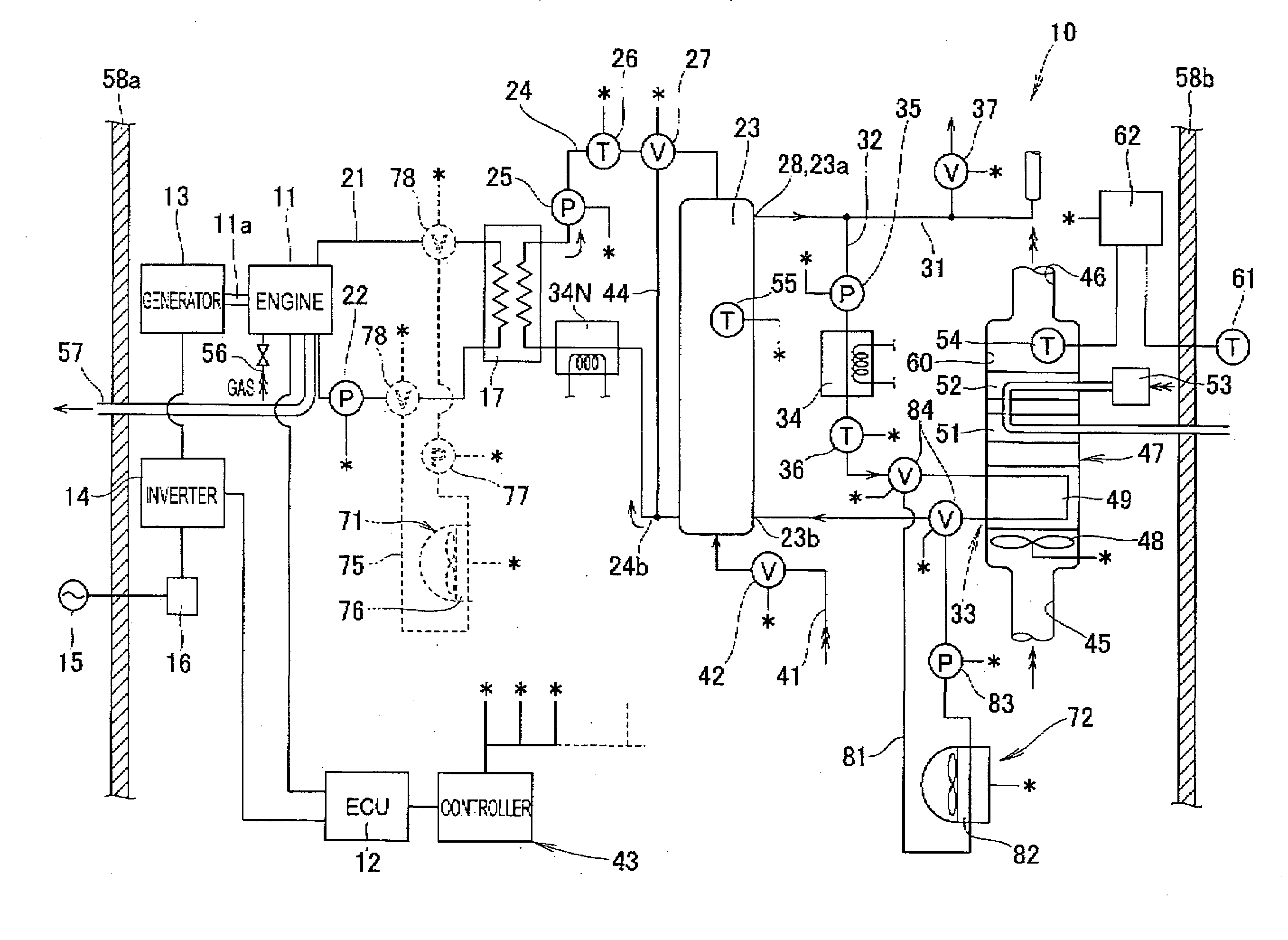
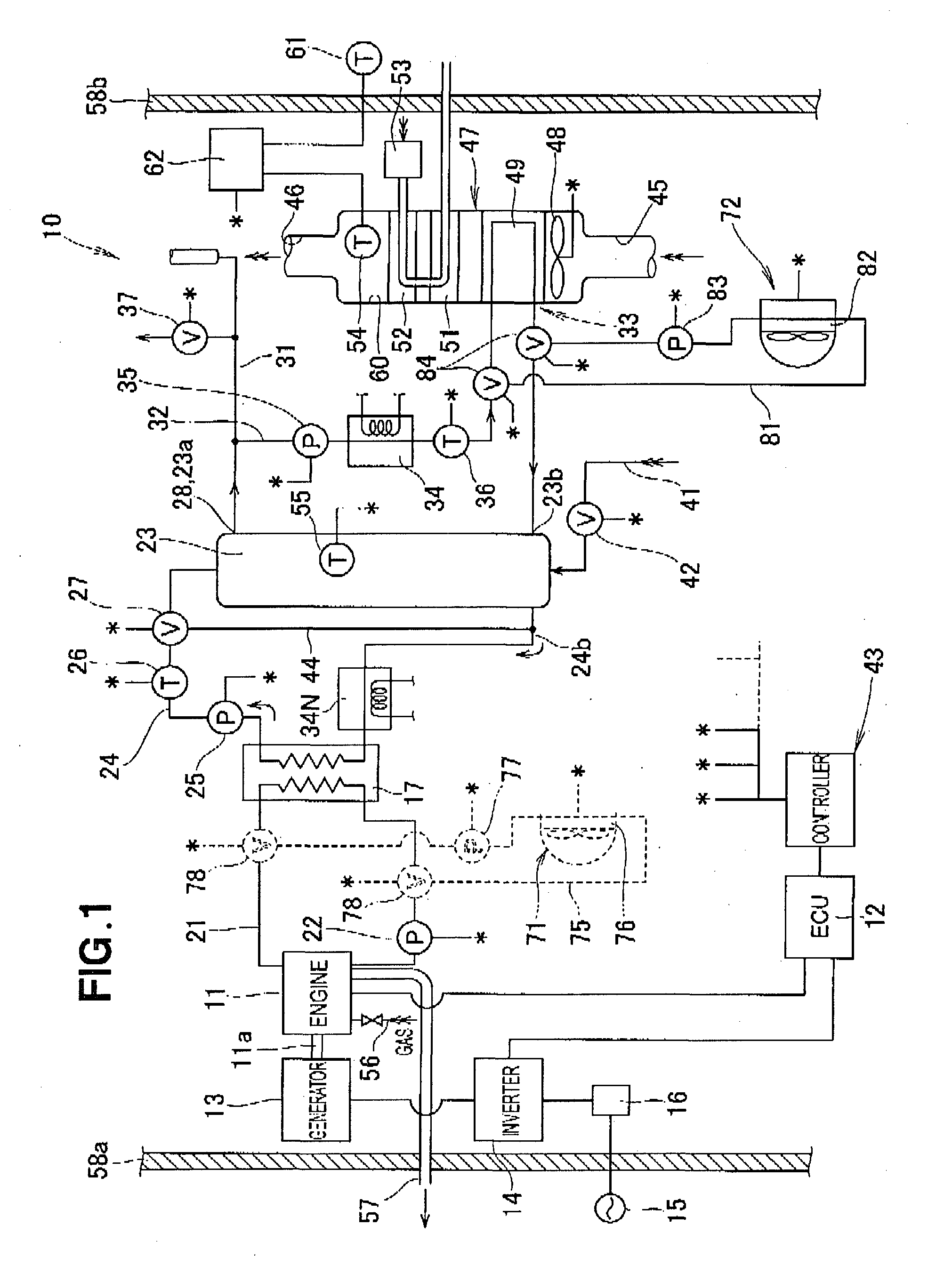
[0017]Referring now to the drawings, wherein like reference characters designate like or corresponding parts throughout the several views, FIG. 1 diagrammatically shows the general configuration of a cogeneration system 10 according to the present invention.

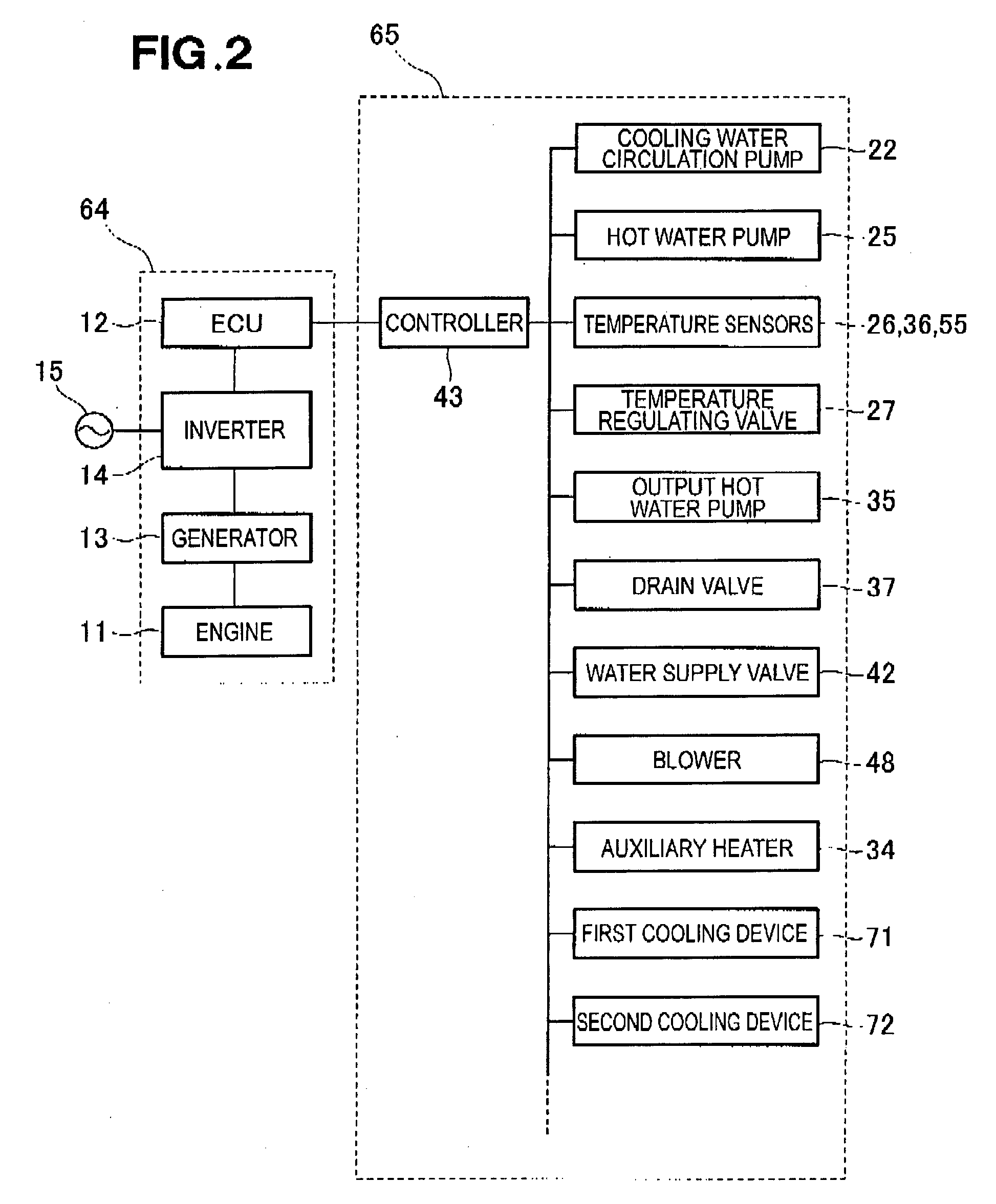
[0018]The cogeneration system 10 generally comprises an engine 11 as a prime mover, an electric control unit (ECU) 12 for controlling the engine 11, a generator 13 connected to an output shaft 11a of the engine 11 and driven by the engine output shaft 11a to generate electric energy (electricity), an inverter unit 14 connected to an output terminal of the generator 13, a changeover switch 16 disposed between the inverter unit 14 and an external commercial power supply 15 to shut off the supply of generated electric energy except when predetermined conditions are met, a waste-heat heat exchanger 17 configured to produce hot water using waste heat from the engine 11 as a heat source and output the hot water therefrom, a cooling wat...

second embodiment

[0043]In the cogeneration system 10′ of the second embodiment, because the first cooling device 71 is activated when the hot water temperature inside the hot water circulation pipe 32 exceeds the first predetermined value, the temperature of the waste-heat heat exchanger 17 is kept below the first predetermined value. This will allow for continuous running of the engine 11, ensuring continuous running of the engine-driven generator 13 leading to stable supply of electric power from the generator 13.


PUM


Abstract

A cogeneration system includes a first cooling device disposed in a cooling water circulation path extending between an engine and a waste-heat heat exchanger, and a second cooling device disposed in a hot water circulation pipe extending between a hot water storage tank and a hot air heater. The first cooling device is activated to cool cooling water when the temperature of hot water stored in the hot water storage tank exceeds a first predetermined value, and the second cooling device is activated to cool the hot water when the temperature of hot air inside the hot air heater exceeds a second predetermined value.

Description

FIELD OF THE INVENTION[0001]The present invention relates to a cogeneration system that generates electricity using an engine-driven generator while recovering waste heat from the engine to supply heat for hot-water supply.BACKGROUND OF THE INVENTION[0002]A typical example of the cogeneration systems of the type concerned is disclosed in, for example, JP 08-004586 A. The disclosed cogeneration system includes a gas engine, a generator driven by the gas engine to generate electric energy, and a hot-water heat exchanger (waste-heat heat exchanger) for transmitting waste heat from the gas engine to cold water to thereby produce hot water.[0003]Basic operation control systems for such cogeneration systems includes a so-called “heat-demand priority type” in which operation pattern of the cogeneration system is set according to an amount of hot-water supply required at the output side of the cogeneration system. In this operation control system, when the demand for hot-water supply is not...

Claims


Application Information

Patent Timeline
IPC IPC(8): F01N5/02F24D18/00
CPCF01P7/165F02G5/00F24D11/005F24D11/009F24D2200/26Y02T10/166Y02E20/14F24H2240/02F24D2220/06F24D2220/08Y02P80/15Y02T10/12F24D18/00F24D2101/70F24D2103/13F24D2103/17
Inventor YURI, NOBUYUKIYAMAMOTO
Owner HONDA MOTOR CO LTD
Why Eureka
Try Eureka