
Light reflex testing device

a light reflex and testing device technology, applied in the field of colorimetric pupil light reflex testing devices, can solve the problems of difficult to find in usable sizes, ambiguous or even incorrect diagnosis, and limited ocular abnormality diagnosis based on pupil light reflexes

Inactive Publication Date: 2009-04-30
BIOMET VISION TECH L C
View PDF1 Cites 4 Cited by
  • Summary
  • Abstract
  • Description
  • Claims
  • Application Information

AI Technical Summary

Benefits of technology

[0014]Advantageously, this invention provides a calorimetric pupil light reflex testing device which is of a low cost and lightweight manufacture.
[0017]Advantageously, this invention provides a colorimetric pupil light reflex testing device which is easy to maintain.
[0020]Advantageously, this invention provides a colorimetric pupil light reflex testing device which focuses and then diffuses light to reduce power consumption requirements.
[0021]Advantageously, this invention provides a colorimetric pupil light reflex testing device which provides longer lasting light sources.
[0022]Advantageously, this invention provides a calorimetric pupil light reflex testing device which allows for quick and easy calibration.

Problems solved by technology

However, in the past, making an ocular abnormality diagnosis based upon pupil-light reflex has been limited by the use of white light only for evaluation of the pupil light reflex which contains both red and blue wavelengths of light.
In addition, prior art filters often “leak” light at undesired wavelengths, which can lead to an ambiguous or even incorrect diagnosis.
Although there are filters which minimize leakage, such filters are typically quite expensive and hard to find in usable sizes.
The efficiency of prior art filters is typically low.
Such lights consume a significant amount of power, generate intense heat, are expensive and require expensive systems to operate effectively.
Also, in time, the incandescent bulbs have a decrease in light output and need to be replaced after a specific hours of usage.
Instruments capable of accurately measuring such luminous are often expensive and difficult to use.
The requirement of a large intensity light source, a specific wavelength filter and a luminance measuring instrument leads to a prior art process requiring a large amount of heavy, complicated and expensive instruments.
Additionally, as such prior art systems typically require hot lights, filters and luminescence meters to be held at various times and at various locations, it is often difficult to conduct a diagnosis with a single individual.
Even if a single individual could accomplish the diagnosis, the prior art process typically does not allow the user a free hand to manipulate the eyelid and / or a camera to record the results.
Utilization of a filter in front of a light source typically leads to a certain amount of variability in the light source being transmitted.
Even with a luminescence meter recording the light passing through the filter, the leakage of the filter combined with the movement of the filter by the user can lead to an indeterminate result.
Yet another drawback associated with the prior art is that given the variability and intensity of prior art machines, prior art machines sometimes require the user to increase the intensity beyond a desirable level to elicit the response necessary for the diagnosis.
Increasing the light intensity beyond the desired diagnostic level, however, can lead to additional damage of the eye.
Conversely, in situations where the power is decreased to avoid damage to the eye, the diagnosis often cannot be made, or the light is left on the pupil for an extended period of time in an effort to elicit the response, thereby again leading to the potential for damage to the eye associated with overexposure.

Method used


Image

  • Light reflex testing device
  • Light reflex testing device
  • Light reflex testing device

Examples


Embodiment Construction

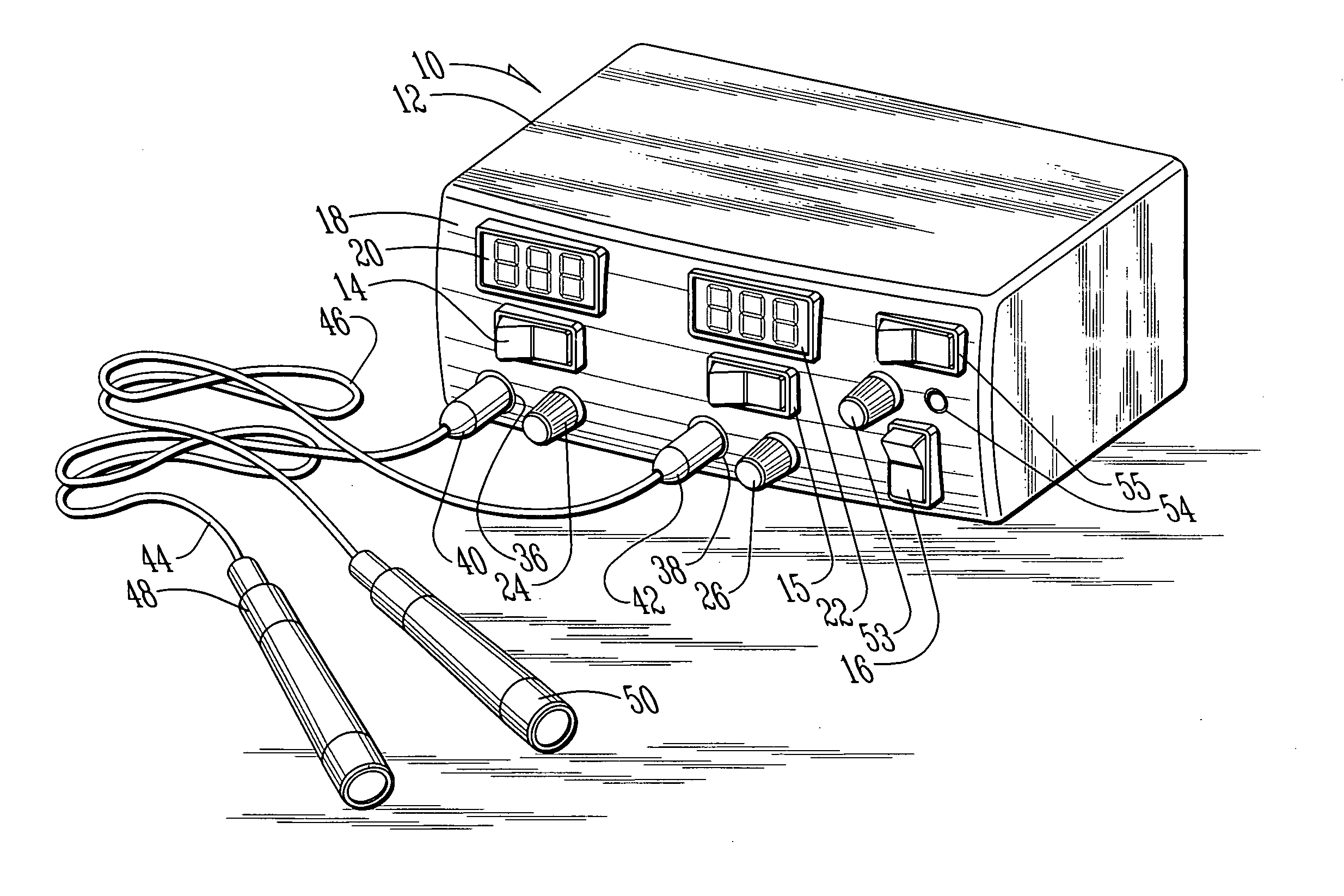
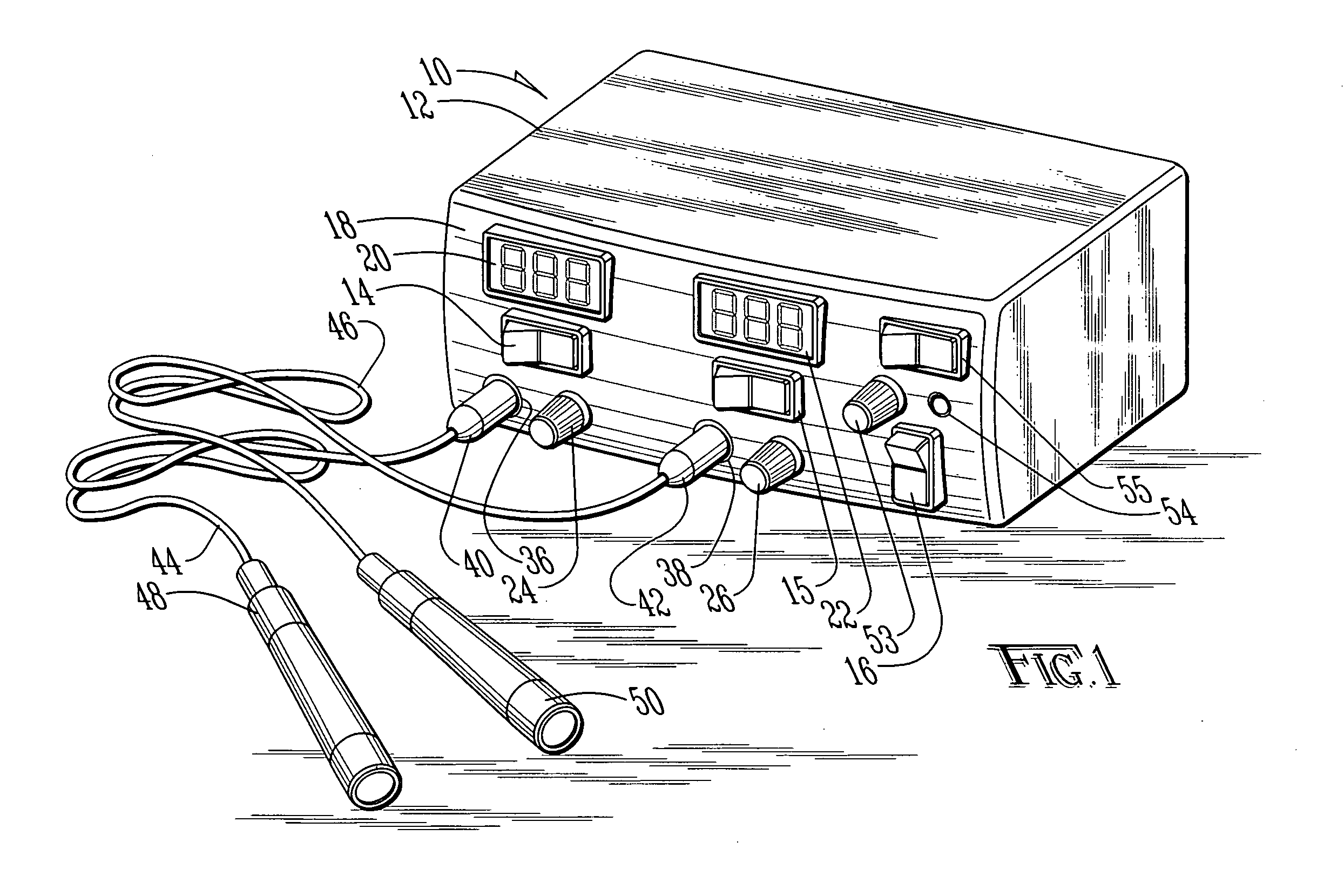
[0036]With reference to the drawings, a colorimetric pupil light reflect testing device is shown generally as (10) in FIG. 1. The device (10) includes a housing (12) which may be constructed of plastic or any suitable material. The housing (12) and all of its internal components preferably weighs less than 10 kilograms and, more preferably less than 5 kilograms. The device (10) includes three rocker switches (14), (15) and (16) which may be of any suitable on / off type known in the art. Provided on the face (18) of the housing (12) are two three and a half digit liquid crystal display (LCD) / voltmeters (20) and (22). The displays may alternatively be light emitting diode displays or any other desired type of display. Provided below the displays (20) and (22) are two potentiometer knobs, (24) and (26).

[0037]Also provided on the housing (12) are two outputs (36) and (38), coupled to a pair of jacks (40) and (42). The jacks (40) and (42) are coupled by power conduits (44) and (46) to a p...


PUM


Abstract

A calorimetric pupil light reflex testing device for diagnostic assessment of the ocular and central nervous system diseases based on melanopsin and non-melanopsin spectral light properties. The device employs blue and red light emitting diodes emitting light at wavelengths of approximately 472 nanometers and 630 respectively to elicit pupillary constriction. The light emitting diodes are each provided within a handheld light wand, allowing the light emitting diodes to be hand held. The light emitting diodes provide intense light and the predetermined wavelengths, thereby eliminating the necessity of a light meter or colored filter.

Description

BACKGROUND OF THE INVENTION[0001]1. Field of the Invention[0002]The present invention relates in general to an ocular diagnostic tool and, more particularly, to an colorimetric pupil light reflex testing device for diagnostic assessment of the ocular and central nervous system diseases based on melanopsin and non-melanopsin spectral light properties.[0003]2. Description of the Prior Art[0004]It is known in the art to diagnose various types of abnormalities in humans and animals using the reaction of a pupil to specific wavelengths of light. The pupil light reflex evaluation provides an objective method for assessing function of the retina and optic nerve. The pupil light reflex is driven by photoreceptor activity (rods and cones) and a subpopulation of retinal ganglion cells, which contain a photosensitive pigment called melanopsin. Physiological spectral properties of healthy retinas provide a baseline against which to use a calorimetric device for testing the pupil for both photor...

Claims


Application Information

Patent Timeline
Patent Type & Authority Applications(United States)
IPC IPC(8): A61B3/10
CPCA61B3/063A61B3/0008
Inventor SUBA, SEBASTIAN S.
Owner BIOMET VISION TECH L C
Learn More