Distributed Spatial Audio Decoder

a spatial audio and decoding technology, applied in the field of surround sound decoding and distribution techniques, can solve the problems of limiting flexibility and scalability of wireless multichannel audio systems, affecting the quality of home wireless audio transmissions, so as to reduce the manufacturing cost and complexity requirements of each module, reduce the cost of each module, and limit the total number of output channels. , the effect of reducing the number of output channels

Active Publication Date: 2009-04-30
CREATIVE TECH CORP
View PDF20 Cites 60 Cited by
  • Summary
  • Abstract
  • Description
  • Claims
  • Application Information

AI Technical Summary

Benefits of technology

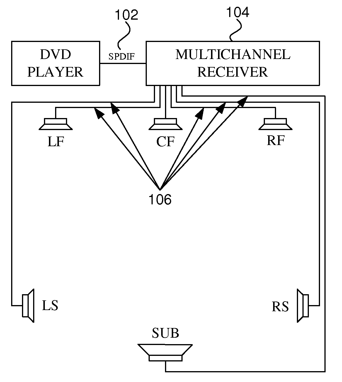
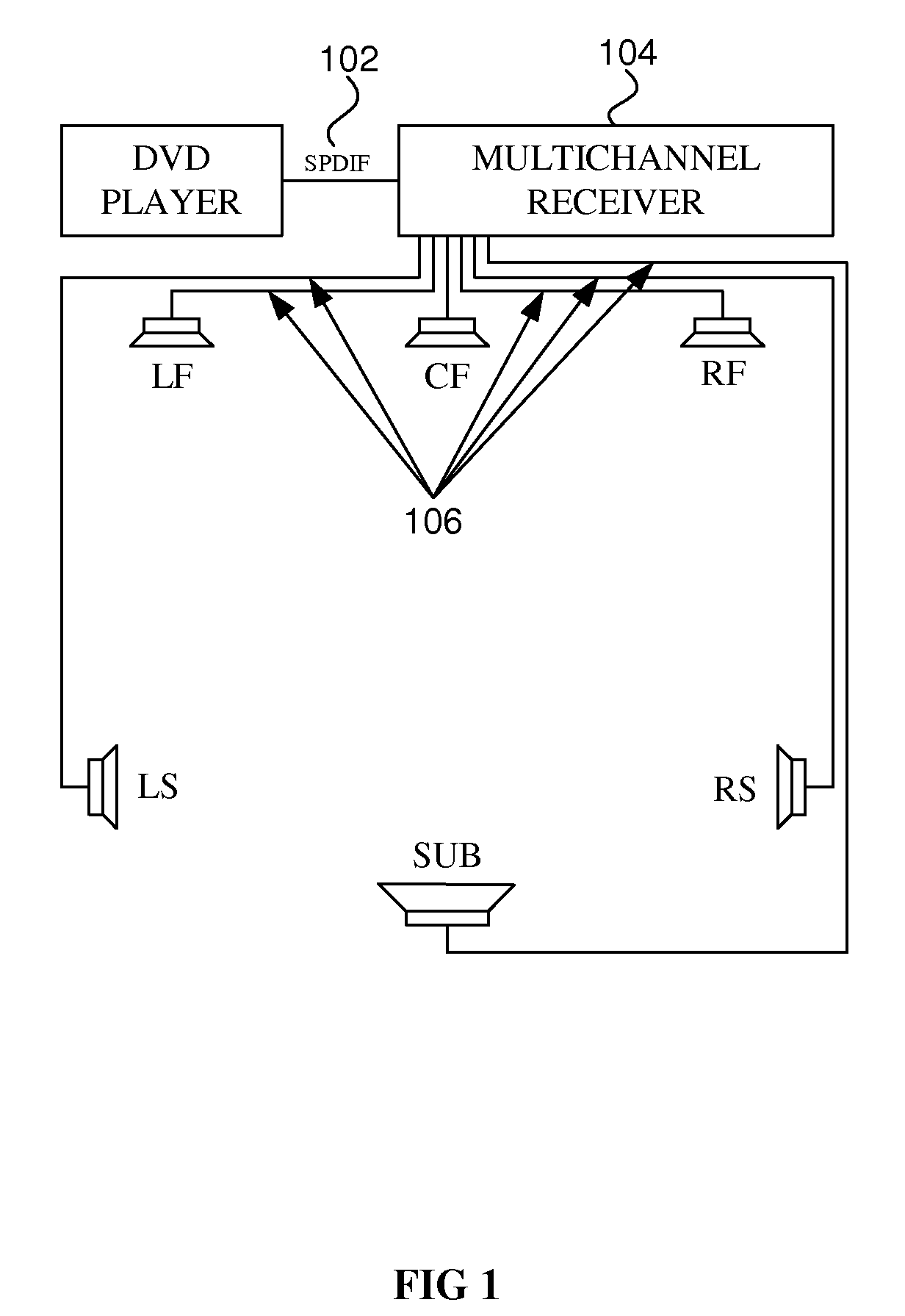
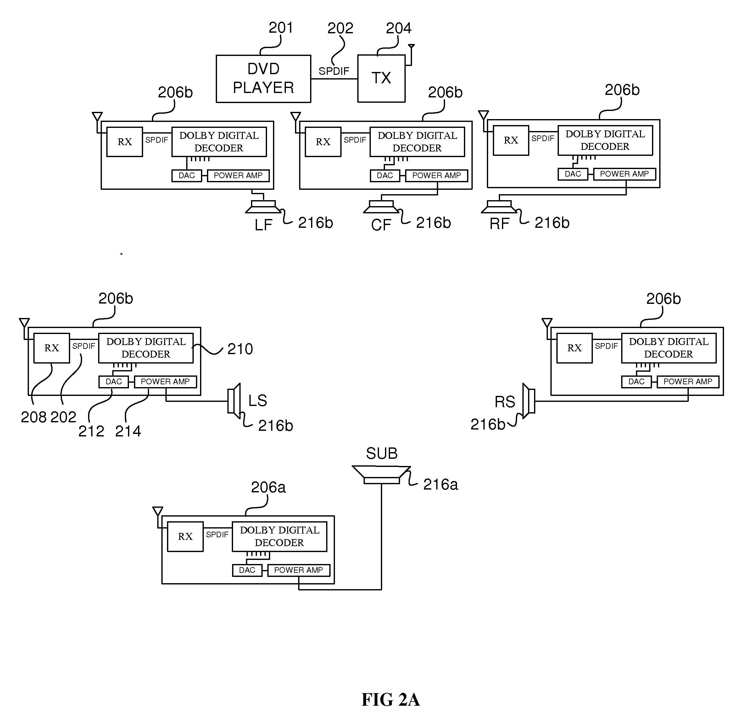
[0012]This invention describes a method for decentralized decoding of a multichannel audio signal by broadcasting the original encoded data and distributing the decoding process between a plurality of receiving units. This allows for the design and manufacture of scalable multichannel audio reproduction systems having an arbitrary number of output channels, composed of a plurality of generic decoder and loudspeaker units each generating fewer output channels. With distributed decoding, a manufacturer can use “off-the-shelf” stereo or mono signal processors, digital-to-analog converters and amplifier components in each generic decoding module, thus reducing manufacturing costs and complexity requirements for each module while offering unlimited scalability in the total number of output channels.

Problems solved by technology

Often, the data rate of home wireless audio transmissions is limited and only allows for the transmission of two channels of audio data, for instance.
This ultimately limits flexibility and scalability in wireless multichannel audio systems.
Furthermore, increasing the number of channels may require replacing common components such as signal processors, digital-to-analog converters, or amplifiers by special (non generic) components, and require the shared multichannel decoder or amplifier unit to have larger cost, power consumption and size.

Method used


Image

  • Distributed Spatial Audio Decoder
  • Distributed Spatial Audio Decoder
  • Distributed Spatial Audio Decoder

Examples


Embodiment Construction

[0022]Reference will now be made in detail to preferred embodiments of the invention. Examples of the preferred embodiments are illustrated in the accompanying drawings. While the invention will be described in conjunction with these preferred embodiments, it will be understood that it is not intended to limit the invention to such preferred embodiments. On the contrary, it is intended to cover alternatives, modifications, and equivalents as may be included within the spirit and scope of the invention as defined by the appended claims. In the following description, numerous specific details are set forth in order to provide a thorough understanding of the present invention. The present invention may be practiced without some or all of these specific details. In other instances, well known mechanisms have not been described in detail in order not to unnecessarily obscure the present invention.

[0023]It should be noted herein that throughout the various drawings like numerals refer to ...


PUM


Abstract

This invention describes a method for decentralized decoding of a multichannel audio signal by broadcasting the original encoded data and distributing the decoding process between a plurality of receiving units. This allows for the design and manufacture of scalable multichannel audio reproduction systems having an arbitrary number of output channels, composed of a plurality of generic decoder and loudspeaker units each generating fewer output channels. With distributed decoding, a manufacturer can use “off-the-shelf” stereo or mono signal processors, digital-to-analog converters and amplifier components in each generic decoding module, thus reducing manufacturing costs and complexity requirements for each module while offering unlimited scalability in the total number of output channels.

Description

CROSS-REFERENCE TO RELATED APPLICATIONS[0001]This application is a continuation-in-part of U.S. patent application Ser. No. 12 / 246,491, filed 6 Oct. 2008, (attorney docket CLIP228US) and entitled “Phase-Amplitude 3-D Stereo Encoder and Decoder”, which claims the benefit of U.S. Provisional Patent Application Ser. No. 60 / 977,432, filed on 4 Oct. 2007, (attorney docket CLIP228PRV) and entitled “Phase-Amplitude Stereo Decoder and Encoder”, and of U.S. Provisional Patent Application Ser. No. 61 / 102,002, filed on 1 Oct. 2008, (attorney docket CLIP228PRV2) and entitled “Phase-Amplitude Stereo Decoder and Encoder”, and which is a continuation-in-part of U.S. patent application Ser. No. 11 / 750,300, filed 17 May 2007, (attorney docket CLIP159US) and entitled “Spatial Audio Coding Based on Universal Spatial Cues”, which claims the benefit of U.S. Provisional Patent Application Ser. No. 60 / 747,532, filed on 17 May 2006, (attorney docket CLIP159PRV) and entitled “Spatial Audio Coding Based on U...

Claims


Application Information

Patent Timeline
Patent Type & Authority Applications(United States)
IPC IPC(8): H04R5/00
CPCG10L19/008H04S1/002G10L19/16H04R2205/024H04R2420/07H04S5/005
Inventor WALSH, MARTINJOT, JEAN-MARCSTEIN, EDWARD
Owner CREATIVE TECH CORP
Why Eureka
Try Eureka