
Fuser member with nano-sized filler

a nano-sized filler and member technology, applied in the field of fuser members, can solve the problems of decreasing the wear rate of the member, prone to yielding copies with noticeable print defects,

Inactive Publication Date: 2009-04-30
XEROX CORP
View PDF25 Cites 20 Cited by
  • Summary
  • Abstract
  • Description
  • Claims
  • Application Information

AI Technical Summary

Benefits of technology

[0025]U.S. Pub. No. 20060269736 discloses a fuser member for fixing a developed image to a copy substrate. The fuser member includes a substrate and thereover an outer coating comprising a haloelastomer and filler particles, wherein said filler particles have a particle size of less than about 3 microns and a hardness of at least about 3 on the Mohs hardness scale.
[0026]In accordance with one aspect of the exemplary embodiment, a fuser member is provided for fixing a developed image to a copy substrate. The fuser member includes a substrate and an outer layer over the substrate. The outer layer includes a halopolymer and filler particles. The filler particles have a particle size of less than 1 micrometer, a hardness of at least 3 on a Mohs hardness scale, and comprise no more than 3 volume percent of the outer layer.
[0027]In accordance with another aspect, an image forming apparatus for forming images on a recording medium includes a charge-retentive surface to receive an electrostatic latent image thereon, a development component to apply toner to said charge-retentive surface to develop an electrostatic latent image to form a developed image on said charge-retentive surface, a transfer film component to transfer the developed image from said charge-retentive surface to a copy substrate, and a fusing component for fusing toner images to a surface of said copy substrate. The fusing component includes a substrate and thereover an outer layer comprising a halopolymer and filler particles, wherein said filler particles have a particle size of less than 1 micrometer and a particle hardness of greater than 3 on a Mohs hardness scale, said filler particles comprising no more than 3 volume percent of said outer layer.

Problems solved by technology

Over time, fuser members coated with, for example, a fluoroelastomer, tend to yield copies which have noticeable print defects, such as gloss variations, due to uneven wear of the coating.
The coupled filler bonds tightly to the fluorocarbon matrix, significantly decreasing the wear rate of the member.

Method used


Image

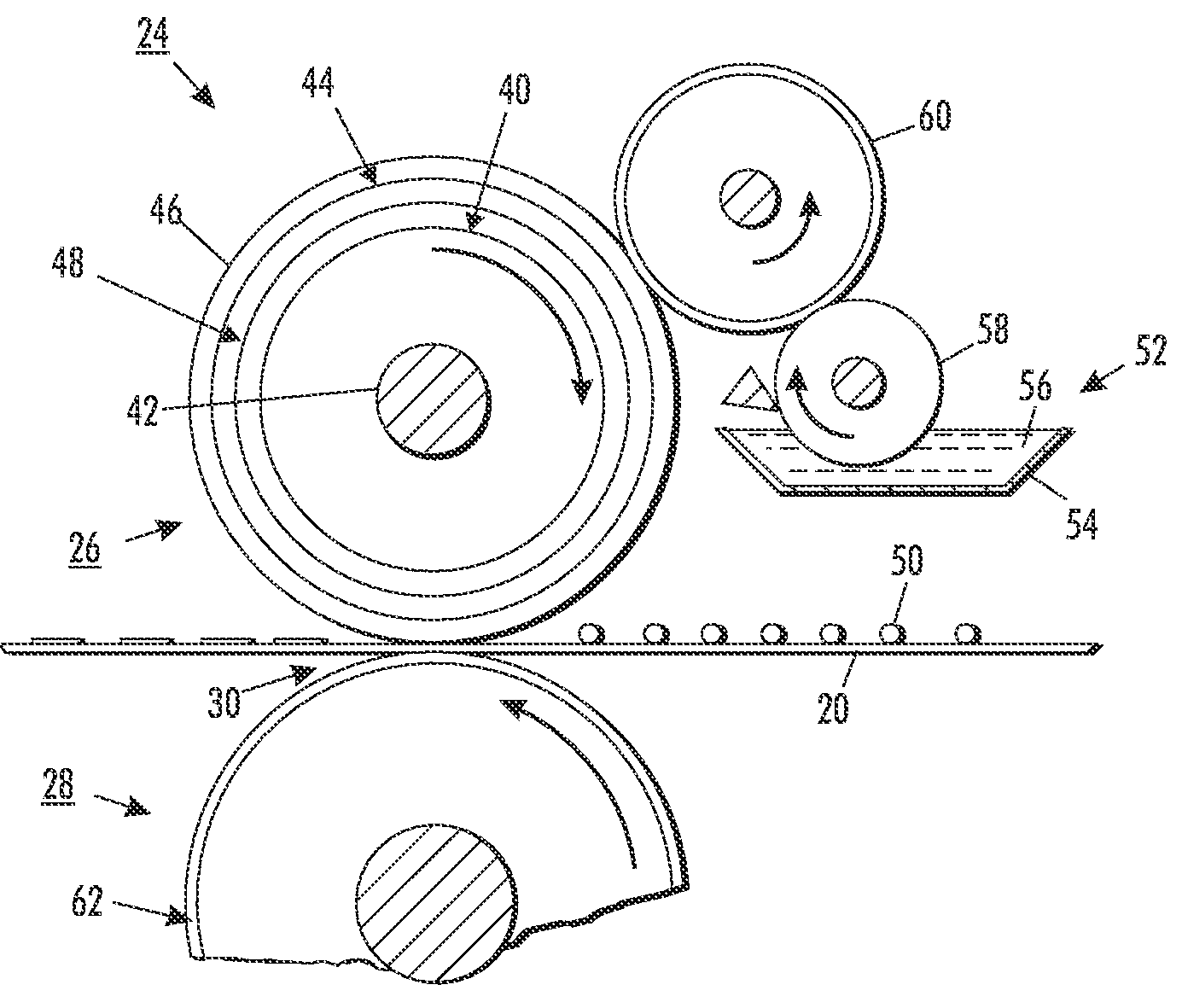
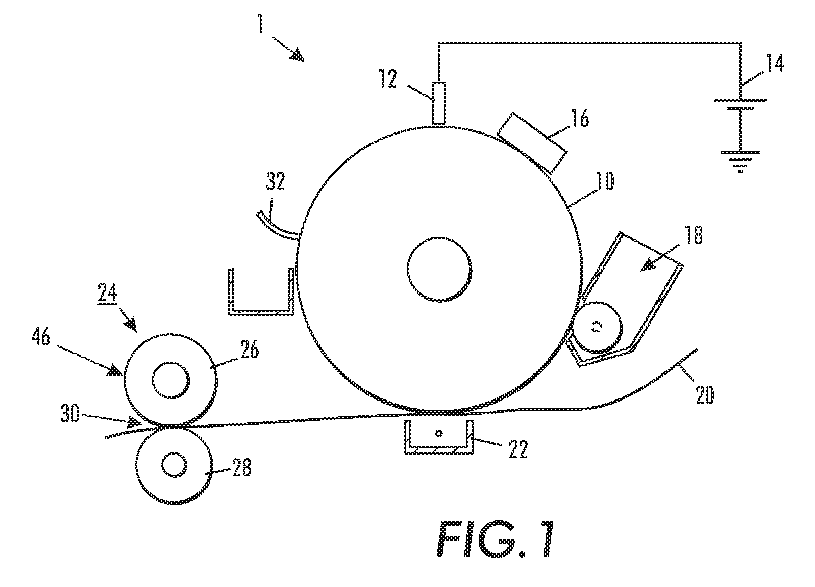
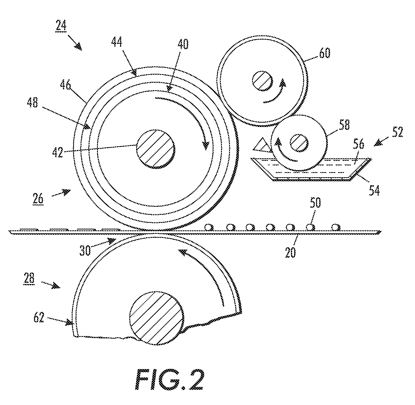
  • Fuser member with nano-sized filler
  • Fuser member with nano-sized filler
  • Fuser member with nano-sized filler

Examples


examples

[0075]A coating is prepared as follows. All parts are per hundred (pph) rubber, by volume, unless otherwise indicated. The following ingredients are employed:

Viton GF 100 parts (Dow-DuPont)Filler4.6 or 7.3 parts of nano particles,such as 50 nm alumina particlesCa(OH)20.75 partsMgO 1.5 partsFC4430 (surfactant)0.75 partsAKE 2900.25 parts(fluorinated silicone fluid)VC50 (curative)  5 parts (Dow-DuPont)

[0076]First, the Viton GF and nano alumina filler are milled in a roll mill. A dispersion is then created by mixing the milled components in MIBK. The dispersion is split into two. The calcium hydroxide and magnesium oxide are milled in a jar mill and added to one half of the dispersion together with the surfactant and fluorinated silicone fluid. VC-50 is added to the other half of the dispersion. Finally, the two halves are brought together, just before applying to a roll, thus forming the coating.

[0077]Rolls are formed by flow coating the coating onto a substrate. Alternatively, a coati...


PUM

PropertyMeasurementUnit
particle sizeaaaaaaaaaa
volume percentaaaaaaaaaa
particle sizeaaaaaaaaaa

Abstract

A fuser member suited to use in a fusing apparatus of an electrostatographic image rendering device includes a substrate and an outer layer over the substrate. The outer layer includes a matrix material and filler particles dispersed in the matrix material. an outer layer comprising a halopolymer and filler particles. The filler particles have a particle size of less than about 1 micrometer and a particle hardness of greater than about 3 on a Mohs hardness scale and form no more than about 3 percent by volume of the outer layer. The outer layer comprising filler particles nonetheless may provide improved wear of the fuser member.

Description

CROSS REFERENCE TO RELATED PATENTS AND APPLICATIONS[0001]The following copending application, the disclosure of which is incorporated herein in its entirety by reference, is mentioned:[0002]Application Ser. No. 11 / 644,624 (Atty Docket No. 20060810-US-NP), filed Dec. 22, 2006 entitled FUSER MEMBER WITH DIAMOND FILLER, by Alan Kuntz, et al.BACKGROUND[0003]The exemplary embodiment relates to fuser members. It finds particular application in connection with a fuser member with a release layer which includes a halopolymer, such as a fluoroelastomer, having nano-sized particles distributed therein.[0004]In a typical xerographic printing device, such as a copier or printer, a photoconductive insulating member is charged to a uniform potential and thereafter exposed to a light image of an original document to be reproduced. The exposure discharges the photoconductive insulating surface in exposed or background areas and creates an electrostatic latent image on the member, which corresponds ...

Claims


Application Information

Patent Timeline
Patent Type & Authority Applications(United States)
IPC IPC(8): G03G15/20
CPCG03G15/2057
Inventor KUNTZ, ALAN RICHARDFINN, PATRICK JAMESCARNEY, RICHARD P.
Owner XEROX CORP
Learn More