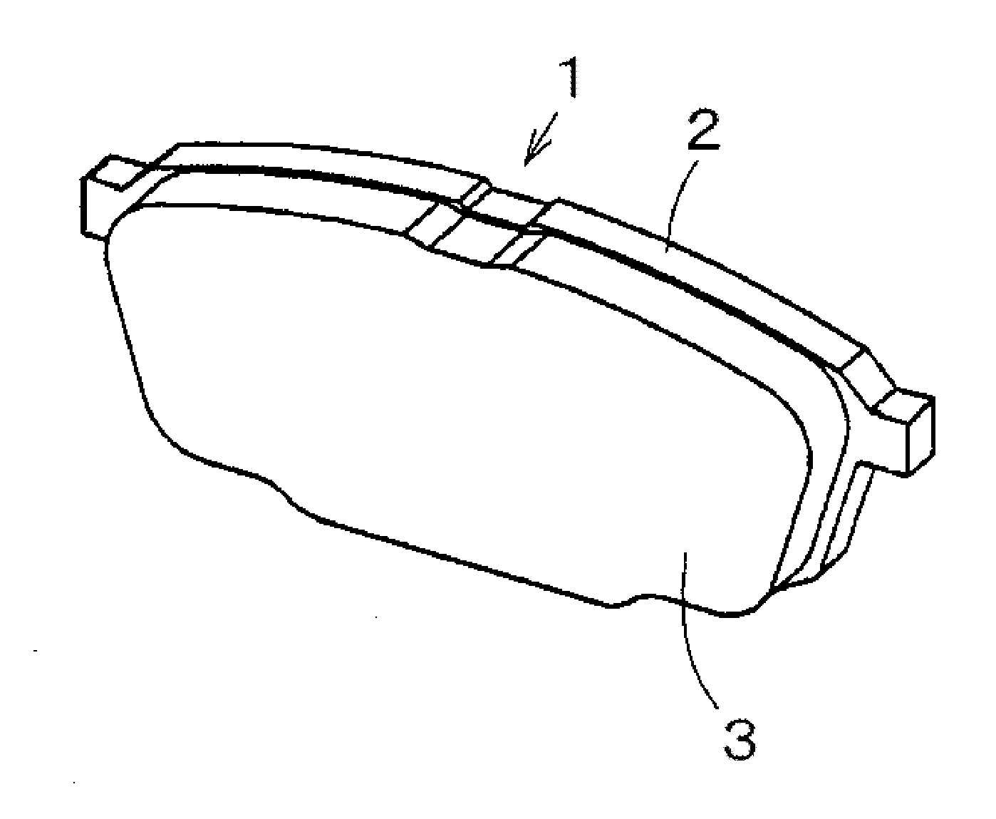
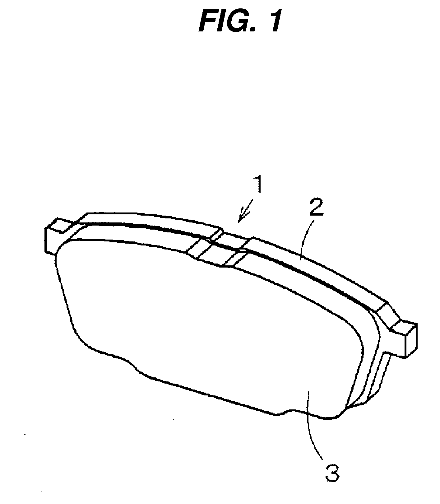
Disc brake pad
a technology of disc brakes and brake pads, applied in the direction of brakes, friction linings, mechanical equipment, etc., can solve the problems of thermal decomposition, sticking problem, generation of unwanted gas, etc., and achieve the effect of effective fading resistance, wear resistance, and formability
Active Publication Date: 2011-10-27
NISSHINBO BRAKE INC
View PDF13 Cites 18 Cited by
- Summary
- Abstract
- Description
- Claims
- Application Information
AI Technical Summary
Benefits of technology
This patent is about a new disc brake pad for a disc brake system that reduces the problem of the brake pad sticking to the ferrous disc rotor during braking. The pad has a friction material that includes a fiber base material, a binder, an abrasive material, and a frictional wear modifier. The friction material also contains a small amount of a thermosetting resin that generates less gas at high temperatures. By adjusting the hardness, particle size, and amount of additional abrasive material, the pad effectively minimizes the sticking problem and provides good fading resistance, wear resistance, and formability. This technology can improve the performance and durability of the disc brake system.
Problems solved by technology
Here, when the frictional temperature of braking creates a high friction surface temperature between the disc rotor and the friction material, a thermosetting resin, included as the binder of the friction material, causes thermal decomposition and the generation of an unwanted gas.
Method used
View moreImage
Smart ImageViewing Examples
Examples
embodiment
This invention will be explained in a concrete manner with actual embodiments and comparative examples; however, this invention is not limited to the following embodiments
Login to View More PUM
| Property | Measurement | Unit |
|---|---|---|
| particle diameter | aaaaa | aaaaa |
| particle diameter | aaaaa | aaaaa |
| particle diameter | aaaaa | aaaaa |
Abstract
To provide a disc brake pad for a disc brake equipped with a metal disc rotor, having a friction material that includes a fiber base material, a binder, an abrasive material, and a frictional wear modifier, which effectively minimizes a sticking problem of the friction material and the disc rotor and simultaneously provides effective fading resistance, wear resistance, and formability. The friction material includes the fiber base material, binder, abrasive material, and frictional wear modifier, and friction material has the binder of 4.5-7.0 weight % relative to the gross friction material amount, aralkyl modified phenolic resin of at least 50 weight % relative to the binder amount, inorganic particles of 1-3 weight % as the abrasive material with 6-8 of Moh's hardness and average particle diameter of 10-200 μm. Furthermore, the friction material includes alkali metal titanate and / or alkali earth metal titanate of 20-30 weight %.
Description
CROSS-REFERENCE TO RELATED APPLICATION(S) AND CLAIM OF PRIORITYThe present application claims the benefit under 35 U.S.C. section 119(a) of Japanese Patent Applications filed in the Japan Patent Office on Apr. 23, 2010 and assigned serial number 2010-100090 and on Mar. 16, 2011 and assigned serial number 2011-057954, the disclosure of which is incorporated herein by reference.FIELD OF INVENTIONThis invention relates to a disc brake pad used in an automotive disc brake, which has a friction material including a fiber base material, a binder, an abrasive material, and a frictional wear modifier.BACKGROUND OF INVENTIONA disc brake is conventionally used for an automotive brake. The conventional disc brake uses a disc brake pad as a frictional member, where the friction material is affixed on a metal base member.Japanese Provisional Patent Publication Number 2006-275198 (Patent Document 1) discloses the disc brake pad formed by affixing the friction material including the fiber base mat...
Claims
Login to View More Application Information
Patent Timeline
 Patent Type & Authority Applications(United States)
IPC IPC(8): F16D65/08
CPCF16D69/026
Inventor HATTORI, YASUKITAKADA, TOSHIYA
Owner NISSHINBO BRAKE INC
Features
- R&D
- Intellectual Property
- Life Sciences
- Materials
- Tech Scout
- Unparalleled Data Quality
- Higher Quality Content
- 60% Fewer Hallucinations
Learn More Browse by: Latest US Patents, China's latest patents, Technical Efficacy Thesaurus, Application Domain, Technology Topic, Popular Technical Reports.
© 2025 PatSnap. All rights reserved.Legal|Privacy policy|Modern Slavery Act Transparency Statement|Sitemap|About US| Contact US: help@patsnap.com


