Burr hole plug designs

a technology of burr hole and plug base, which is applied in the field of burr hole plug designs, can solve the problems of repositioning—a time-consuming process, and reducing the effect of patient therapy, and achieves the effects of reducing the number of patients

Inactive Publication Date: 2009-04-30
BOSTON SCI NEUROMODULATION CORP
View PDF52 Cites 79 Cited by
  • Summary
  • Abstract
  • Description
  • Claims
  • Application Information

AI Technical Summary

Benefits of technology

[0027]The burr hole plug further comprises a retainer configured for being mounted within the aperture of the plug base to secure the medical device, such that the retainer is at least partially recessed within the burr hole. In one embodiment, the flange has a bottom surface and the retainer is configured for extending below the bottom surface of the flange. While the present invention should not be so limited in their broadest aspects, the recession of the retainer into the burr hole allows the profile (i.e., height) of the burr hole plug to be reduced. In one embodiment, the retainer is configured for being removably mounted within the aperture of the plug base.
[0054]The burr hole plug further comprises a retainer configured for being mounted within the aperture of the plug base. In one embodiment, the retainer is configured for being removably mounted within the aperture of the plug base. In another embodiment, the plug base includes at least one inner annular ledge configured for supporting the retainer when mounted within the aperture of the plug base. The retainer further includes first and second slidable clamping mechanisms configured for securing the medical devices therebetween within the aperture of the plug base. While the present inventions should not be so limited in their broadest aspects, the use of two slidable clamping mechanisms conveniently facilitates the securing of more than one medical device within a single cranial burr hole. For example, the first and second slidable clamping mechanisms can be configured for securing the medical devices along any one of a plurality of chords of the aperture of the plug base.

Problems solved by technology

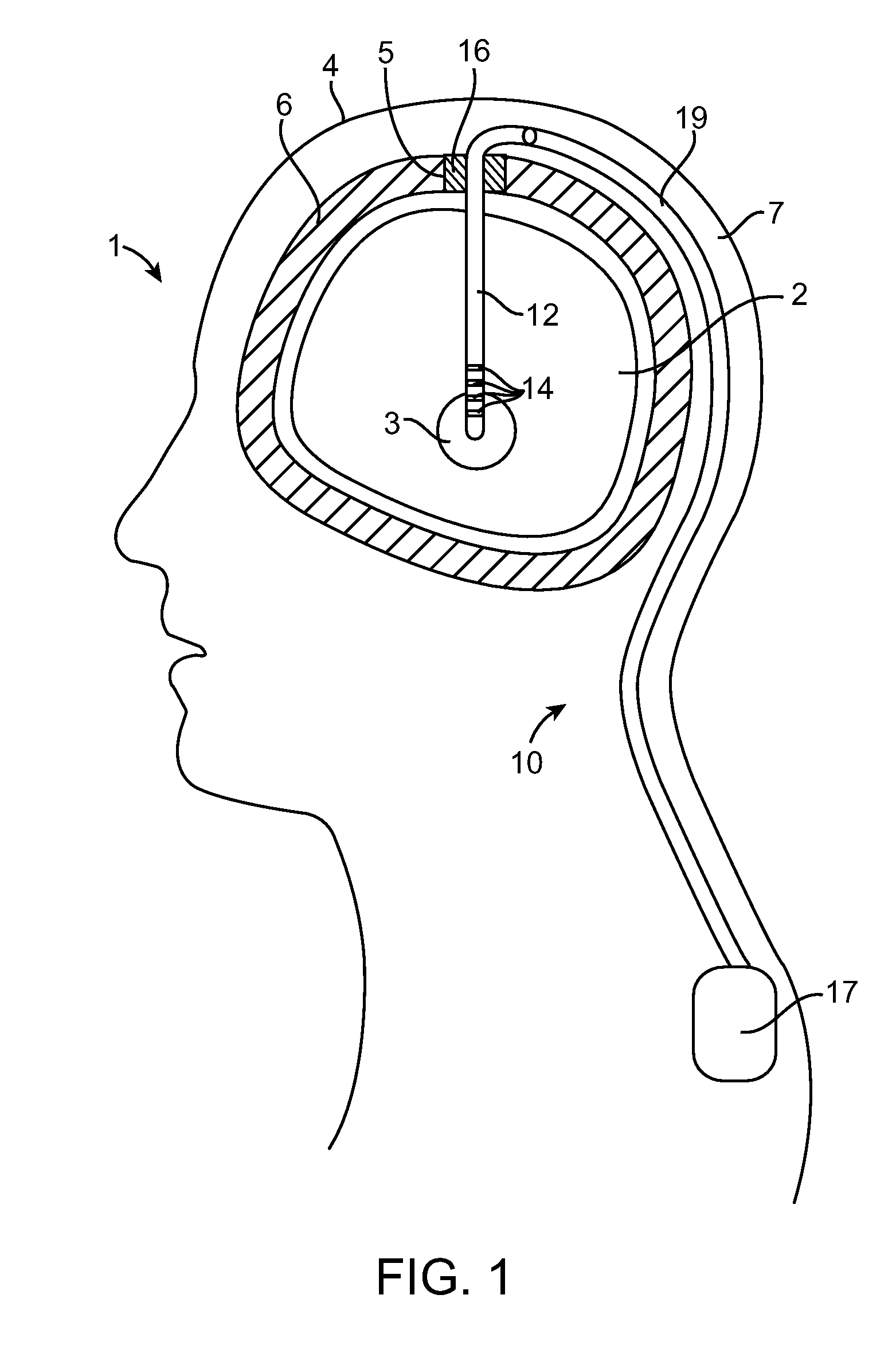
Thus, lead displacements of less than a millimeter may have a deleterious effect on the patient's therapy.
Notably, any displacement of the portion of the lead exiting the burr hole will result in the translation of the electrodes positioned in the brain relative to the target site, thereby requiring the lead to be repositioned—a time-consuming process.
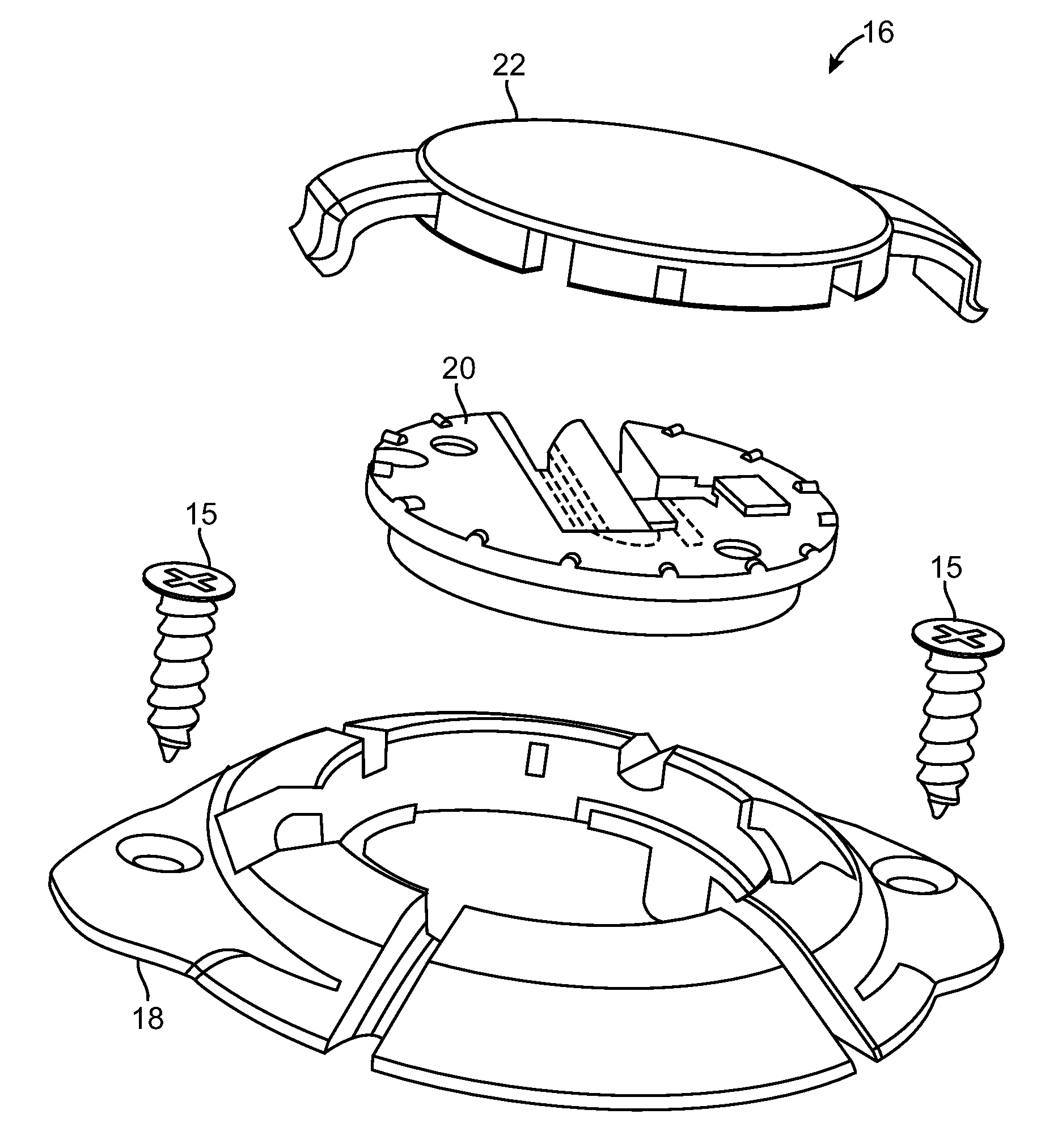
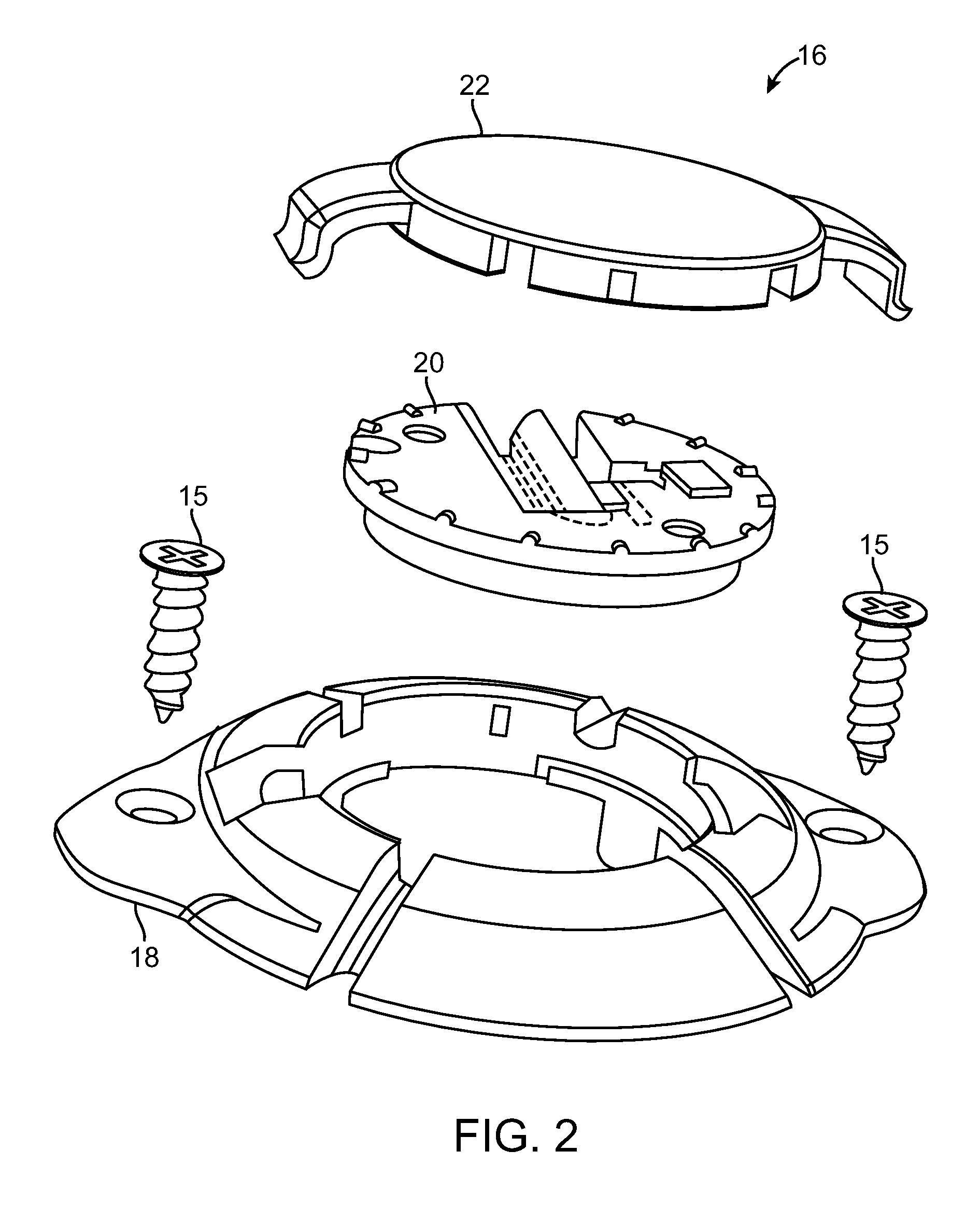
Also, because prior art plug bases are composed of a single piece, there is a risk that the plug base may fracture if the plug base is anchored to tightly to the cranium of the patient, especially if the bottom surface of the plug base does not match the curvature of the cranium.
In addition, because the clamping mechanism will deform somewhat along its length when clamped against the stimulation lead, an unequal force may be applied along the clamping mechanism, thereby weakening the retention force applied to the lead.
Also, because of the relatively weak composition of the retainer, the clamping force between it and the mating surface of the disk is limited, thereby limiting the lead retention force of the clamping mechanism.
Furthermore, because the application of a downward force is typically necessary to unlock and allow the clamping mechanism to rotate relative to the disk, such downward force may cause the clamping mechanism to be bent too far down, thereby permanently deforming or breaking it.
In addition, since burr hole plugs are typically composed of biocompatible polymers that are extremely lubricious, particularly when wetted, the coefficient of friction of the retention surface of the clamping mechanism, as well as the mating surface of the disk, may be relatively low.
As another example of a problem suffered from prior art burr hole plugs, the retainer may rotate within the plug base, potentially resulting in the inadvertent movement of the stimulation lead from the target site.
However, prior art burr hole plugs are not designed to stabilize more than one stimulation lead at time.
By creating multiple burr holes, the risk to the patient, time in the operating room (which also increases patient risk), the materials and staff needed in the operating room, and cost of the procedure are all increased, so a burr hole plug that can accommodate multiple leads through one burr hole is preferred.
However, because the recess of the plug base in which the lead is seated may be located obliquely (as opposed to perpendicular) to the slot, it may be difficult to bend the lead perpendicular to the slot towards the base recess if the lead support mechanism is not perfectly oriented relative to the plug base.
In addition, rotation of the lead support mechanism relative to the base while the lead is seated within the base recess may cause the lead to be displaced from the target site.
However, due to the diminutive size of the burr hole plug components, they are difficult to position, manipulate, and handle.
This, in combination with the limited working space between the targeting apparatus and the burr hole, makes it quite difficult to visualize and correctly install the plug within the burr hole and stabilize the lead.
While the surgeon is installing the components of the burr hole plug, there is a risk of foreign objects (screws, tools, debris, etc.) falling into the exposed burr hole, as well as slippage of tools within the burr hole.
However, the screws often pop-out of these tools unintentionally and do not always screw into the cranium at the correct angle.
Thus, installation of the burr hole plug without disturbing the lead position is nearly an impossible task without specialization of the tools and / or burr hole plug that can center the plug base while it is anchored to the patient's skull and securely hold and mount the retainer to the plug base.
However, this installation tool only engages the retaining disk at one location.
Thus, it is possible that the disk may become skewed or tilted while attempting to install it within the plug base, or worse yet, given the spring force stored in the disk, it may be launched from the surgical site.
If the diameter of the actual lead used with the burr hole plug is smaller than this intended, the retention force applied to the lead by the clamping mechanism will not be sufficient.
If the diameter of the actual lead used with the burr hole plug is greater than this intended diameter, too much force will need to be applied to the lead in order to place the clamping mechanism within the locking position, thereby potentially damaging the retainer and / or the lead.
As yet another example, once the plug base is mounted to the patient's cranium via screws, it is difficult to adjust the position of the plug base if it is desired.
Also, due to the relatively large size of the stereotactic targeting apparatus, there is often little working space available between the targeting apparatus and the burr hole to anchor the plug base to the cranium of the patient.

Method used


Image

  • Burr hole plug designs
  • Burr hole plug designs
  • Burr hole plug designs

Examples


Embodiment Construction

[0159]Turning first to FIG. 1, an exemplary DBS system 10 constructed in accordance with one embodiment of the present inventions is shown implanted within a patient for the treatment of a debilitating disease such as, Parkinson's disease, dystonia, essential tremor, seizure disorders, obesity, depression, etc. The system 10 comprises a stimulation lead 12 implanted within the parenchyma of the brain 2 of a patient 1 in order to position electrodes 14 carried by the distal end of the stimulation lead 12 adjacent a target tissue region 3, such as a deep brain structure of the patient (e.g., the ventrolateral thalamus, internal segment of globus pallidus, substantia nigra pars reticulate, subthalamic nucleus, or external segment of globus pallidus). Thus, electrical stimulation energy can be conveyed from the electrodes 14 to the target tissue region 3 to treat the disease. As can be seen, the stimulation lead 12 is introduced into the head 4 of the patient 1 via a burr hole 5 formed ...


PUM


Abstract

A burr hole plug comprises a plug base including a flange configured for being mounted around a burr hole, an aperture through which an elongated medical device may pass, and tabs configured for extending within the cranial burr hole to center the plug base relative to the cranial burr hole. The burr hole plug further comprises a retainer configured for being mounted within the aperture of the plug base to secure the medical device. A method may comprise locating the plug base within a burr hole, such that the tabs are disposed within the burr hole to center the plug base relative to the cranial burr hole, introducing the elongated medical device through the cranial burr hole and into the brain tissue of the patient, mounting the retainer within the aperture of the plug base, and actuating the retainer to secure the medical device.

Description

RELATED APPLICATION DATA[0001]The present application claims the benefit under 35 U.S.C. § 119 to U.S. Provisional Patent Application Ser. No. 60 / 983,099, filed Oct. 26, 2007. The foregoing application is hereby incorporated by reference into the present application in its entirety.FIELD OF THE INVENTION[0002]The present inventions relate to apparatus for securing elongated medical devices, such as catheters or leads, within a cranial burr hole.BACKGROUND OF THE INVENTION[0003]Deep brain stimulation (DBS) and other related procedures involving implantation of electrical stimulation leads within the brain of a patient are increasingly used to treat disorders, such as Parkinson's disease, dystonia, essential tremor, seizure disorders, obesity, depression, restoration of motor control, and other debilitating diseases via electrical stimulation via stimulation of one or more target sites, including the ventrolateral thalamus, internal segment of globus pallidus, substantia nigra pars re...

Claims


Application Information

Patent Timeline
Patent Type & Authority Applications(United States)
IPC IPC(8): A61F2/02A61F2/28
CPCA61N1/0539A61N1/0534A61B19/20A61B17/0057A61B2019/208A61B2090/103A61B90/10
Inventor LANE, COURTNEYGEROY, JESSEMAKOUS, JAMES C.WHITEHURST, TODDFLOWERS, MATTHEWBARKER, JOHN MICHAELFERRELL, TERRYSWOYER, JOHNSCHLEICHER, BRETTGAGNON, JEFFDIGIORE, ANDREWGARAI, ELLISJAAX, KRISTENCARBUNARU, RAFAEL
Owner BOSTON SCI NEUROMODULATION CORP
Why Eureka
Try Eureka