Control system for internal combustion engine

a control system and internal combustion engine technology, applied in the direction of electrical control, process and machine control, instruments, etc., can solve the problems of not taking into account the insufficient amount of preventing the deterioration of the combustion state, and the possibility of high possibility of combustion state deterioration

Inactive Publication Date: 2009-04-30
HONDA MOTOR CO LTD
View PDF8 Cites 12 Cited by
  • Summary
  • Abstract
  • Description
  • Claims
  • Application Information

AI Technical Summary

Benefits of technology

[0015]With this configuration, the maximum opening is corrected in the decreasing direction when the auxiliary fuel supply means is determined to be abnormal. Therefore, it is possible to certainly avoid inconvenience such as an engine stall when the auxiliary fuel supply means has become abnormal.

Problems solved by technology

In the internal combustion engine in which fuel containing alcohol is used, the combustion state may deteriorate with high possibility especially when the accelerator pedal is greatly depressed immediately after the cold start of the engine and the throttle valve is opened according to the depression amount.
However, a problem of deterioration of the combustion state is not taken into consideration.
Further, in the device of JP-'742, the engine coolant temperature is taken into consideration, which is, however, not sufficient for preventing the combustion state from deteriorating.

Method used


Image

  • Control system for internal combustion engine
  • Control system for internal combustion engine
  • Control system for internal combustion engine

Examples


first embodiment

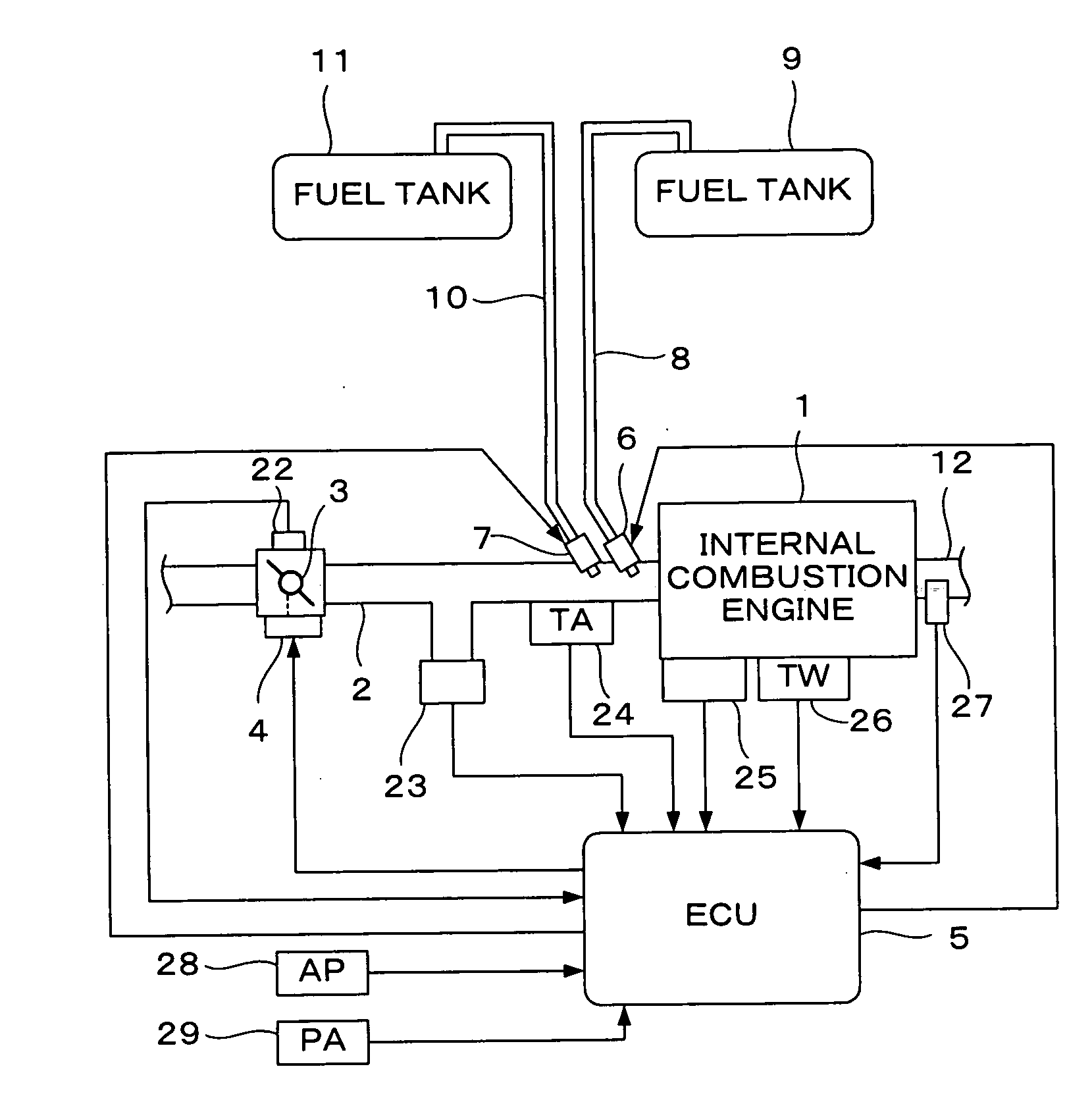
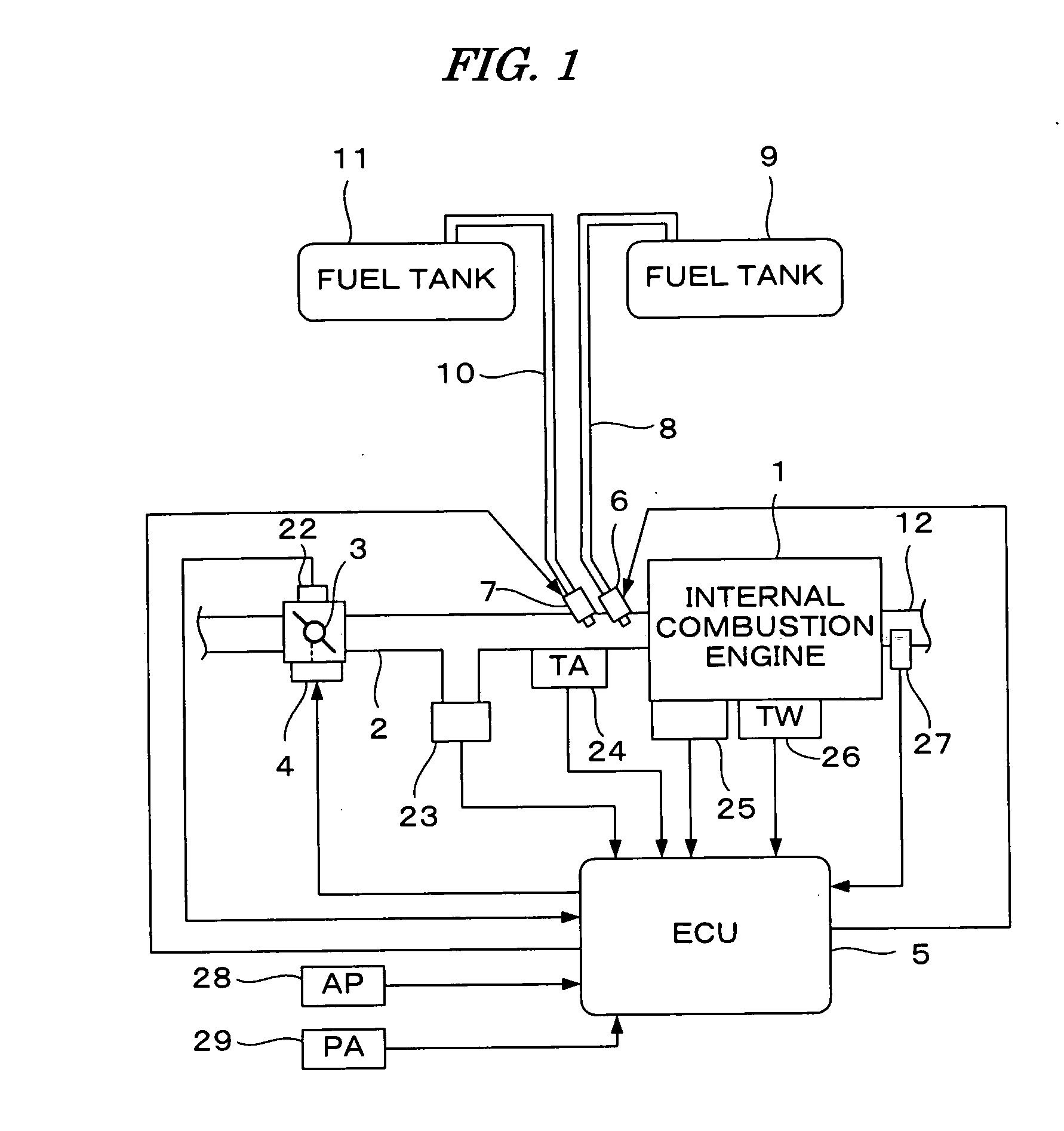
[0028]FIG. 1 is a schematic diagram showing a configuration of an internal combustion engine and a control system therefor according to a first embodiment of the present invention. The internal combustion engine (hereinafter referred to as “engine”) 1 can be a 4-cylinder engine which can be operated using alcohol, gasoline, or gasohol (mixture of alcohol and gasoline) as fuel. The engine 1 has an intake pipe 2 provided with a throttle valve 3. An actuator 4 for actuating the throttle valve 3 can be connected to the throttle valve 3, and the actuator 4 is connected to an electronic control unit (hereinafter referred to as “ECU”) 5. The ECU 5 controls an opening TH of the throttle valve 3 through the actuator 4. A throttle valve opening sensor 22 for detecting a throttle valve opening TH is connected to the throttle valve 3, and the detection signal of the throttle valve opening sensor 22 is supplied to the ECU 5.

[0029]A fuel supply system for supplying fuel to the engine 1 can includ...

second embodiment

[0067]FIG. 9 is a schematic diagram showing a configuration of an internal combustion engine and a control system therefor according to a second embodiment of the present invention. The configuration shown in FIG. 9 is obtained by deleting the auxiliary fuel supply device shown in FIG. 1, i.e., the auxiliary fuel injection valve 7, the auxiliary fuel passage 10, and the auxiliary fuel tank 11. The configuration shown in FIG. 9 is the same as that shown in FIG. 1 except for the above-described point. That is, in this embodiment, the auxiliary fuel is not used and the engine 1 is operated using only the main fuel. The present embodiment is the same as the first embodiment except for the points described below.

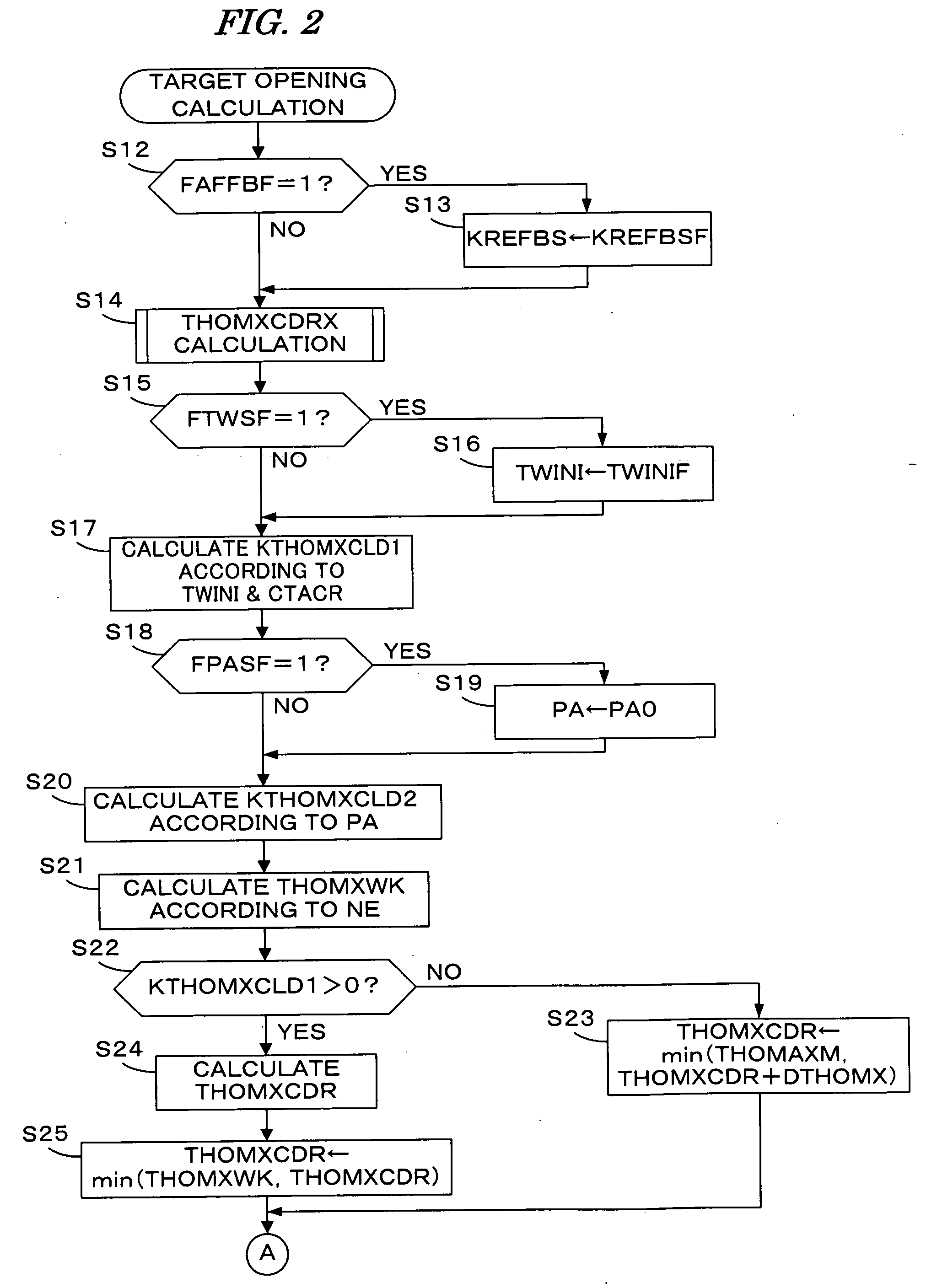
[0068]FIG. 10 is a flowchart of the target opening calculation process in this embodiment. This process is obtained by changing steps S14 and S24 of FIG. 2 respectively to steps S14a and S24a.

[0069]In step S14a, a THOMXCDRS calculation process shown in FIG. 11 is performed to ca...


PUM


Abstract

A control system for an internal combustion engine in which fuel containing alcohol is used. In the control system, a maximum opening of a throttle valve of the engine is set, and a target opening of the throttle valve is set to a value which is equal to or less than the maximum opening. An opening of the throttle valve is controlled so as to coincide with the target opening. The maximum opening is according to a concentration parameter indicative of a concentration of alcohol in the fuel, a temperature parameter indicative of a temperature of the engine, and a number of ignitions performed after start of the engine.

Description

BACKGROUND OF THE INVENTION[0001]1. Field of the Invention[0002]The present invention relates to a control system for an internal combustion engine, and particularly to a control system for an internal combustion engine in which fuel containing alcohol is used.[0003]2. Description of the Related Art[0004]Japanese Patent Laid-open No. H3-253733 (JP-'733) discloses a method for controlling a throttle valve opening in an internal combustion engine in which alcohol, gasoline, or composite fuel of alcohol and gasoline (gasohol) is used. According to this control method, a target throttle valve opening is set according to a concentration of alcohol in the fuel, a depression amount of an accelerator pedal, and an engine rotational speed, so that constant drivability of the engine (engine output) is obtained regardless of the concentration of alcohol in the fuel. Further, an actual throttle valve opening is controlled to coincide with the target throttle valve opening.[0005]Further, Japanes...

Claims


Application Information

Patent Timeline
Patent Type & Authority Applications(United States)
IPC IPC(8): F02D41/30
CPCF02D19/0631F02D19/088F02D41/0002F02D41/0025F02D41/064F02D41/1495F02D41/1498F02D41/221F02D41/222F02D2011/102F02D2200/0612F02D2200/1015F02D2250/26F02M43/00Y02T10/36Y02T10/42F02D19/0623F02D19/0665F02D19/0692F02D19/084F02D19/081Y02T10/30Y02T10/40
Inventor KAWAMURA, KAZUNORINISHIOKA, FUTOSHIKITAMURA, OSAMU
Owner HONDA MOTOR CO LTD
Why Eureka
Try Eureka